|
|
|
PDF 74ACTQ657 Data sheet ( Hoja de datos )
| Número de pieza | 74ACTQ657 | |
| Descripción | Quiet Series Octal Bidirectional Transceiver | |
| Fabricantes | Fairchild Semiconductor | |
| Logotipo | ||
Hay una vista previa y un enlace de descarga de 74ACTQ657 (archivo pdf) en la parte inferior de esta página. Total 10 Páginas | ||
|
No Preview Available !
January 1990
Revised September 2000
74ACQ657 • 74ACTQ657
Quiet Series Octal Bidirectional Transceiver with
8-Bit Parity Generator/Checker and 3-STATE Outputs
General Description
The ACQ/ACTQ657 contains eight non-inverting buffers
with 3-STATE outputs and an 8-bit parity generator/
checker. Intended for bus oriented applications, the device
combines the 245 and the 280 functions in one package.
The ACQ/ACTQ utilizes Fairchild Quiet Series technol-
ogy to guarantee quiet output switching and improved
dynamic threshold performance. FACT Quiet Series fea-
tures GTO output control and undershoot corrector in
addition to a split ground bus or superior performance.
Features
s Guaranteed simultaneous switching noise level and
dynamic threshold performance
s Guaranteed pin-to-pin skew AC performance
s Combines the 245 and the 280 functions in one package
s 300 mil 24-pin slim dual-in-line package
s Outputs source/sink 24 mA
s ACTQ has TTL-compatible inputs
Ordering Code:
Order Number Package Number
Package Description
74ACQ657SPC
N24C
24-Lead Plastic Dual-In-Line Package (PDIP), JEDEC MS-001, 0.300 Wide
74ACTQ657SC
M24B
24-Lead Small Outline Integrated Circuit (SOIC), JEDEC MS-013, 0.300 Wide
74ACTQ657SPC
N24C
24-Lead Plastic Dual-In-Line Package (PDIP), JEDEC MS-001, 0.300 Wide
Device also available in Tape and Reel. Specify by appending suffix letter “X” to the ordering code
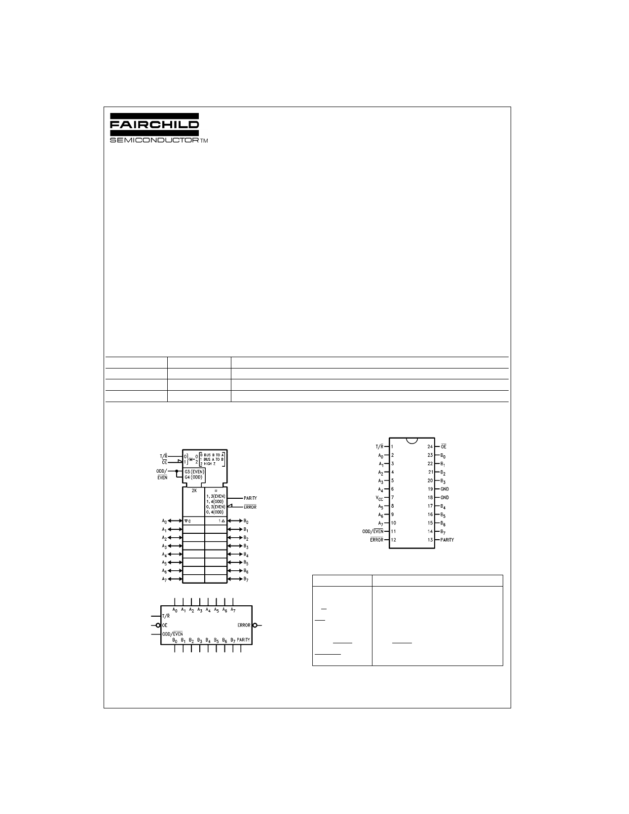
Logic Symbols
Connection Diagram
IEEE/IEC
Pin Descriptions
Pin Names
A0–A7
B0–B7
T/R
OE
PARITY
ODD/EVEN
ERROR
Description
Data Inputs/3-STATE Outputs
Data Inputs/3-STATE Outputs
Transmit/Receive Input
Enable Input
Parity Input/3-STATE Output
ODD/EVEN Parity Input
Error 3-STATE Output
FACT, Quiet Series, FACT Quiet Series, and GTO are trademarks of Fairchild Semiconductor Corporation.
© 2000 Fairchild Semiconductor Corporation DS010636
www.fairchildsemi.com
1 page 
DC Electrical Characteristics for ACQ (Continued)
Symbol
Parameter
VCC
TA = +25°C
TA = −40°C to +85°C Units
(V) Typ
Guaranteed Limits
Conditions
VOLV
VIHD
Quiet Output Minimum
Dynamic VOL
Minimum HIGH Level Dynamic
Input Voltage
5.0
−0.6
−1.2
5.0 3.1 3.5
Figures 1, 2
V
(Note 5)(Note 6)
V (Note 5)(Note 7)
VILD
Maximum LOW Level Dynamic
Input Voltage
5.0 1.9 1.5
V (Note 5)(Note 7)
Note 2: Maximum of 8 outputs loaded; thresholds on input associated with output under test.
Note 3: Maximum test duration 2.0 ms, one output loaded at a time.
Note 4: IIN and ICC @ 3.0V are guaranteed to be less than or equal to the respective limit @ 5.5V VCC.
Note 5: DIP package.
Note 6: Max number of outputs defined as (n). Data Inputs are driven 0V to 5V. One output @ GND.
Note 7: Max number of Data Inputs (n) switching. (n−1) Inputs switching 0V to 5V (ACQ).Input-under-test switching: 5V to threshold (VILD),
0V to threshold (VIHD) f = 1 MHz.
DC Electrical Characteristics for ACTQ
Symbol
Parameter
VCC
TA = +25°C
TA = −40°C to +85°C Units
(V) Typ
Guaranteed Limits
Conditions
VIH Minimum HIGH Level
Input Voltage
VIL Maximum LOW Level
Input Voltage
VOH Minimum HIGH Level
Output Voltage
4.5 1.5 2.0 2.0 V VOUT = 0.1V
5.5 1.5 2.0
2.0
or VCC − 0.1V
4.5 1.5 0.8 0.8 V VOUT = 0.1V
5.5 1.5 0.8
0.8
or VCC − 0.1V
4.5 4.49 4.4
4.4
5.5 5.49 5.4 5.4 V IOUT = −50 µA
VOL Maximum LOW Level
Output Voltage
4.5 3.86
5.5 4.86
4.5 0.001 0.1
5.5 0.001 0.1
3.76
4.76
0.1
0.1
VIN = VIL or VIH
V IOH = −24mA
IOH = −24 mA (Note 8)
V IOUT = 50 µA
IIN Maximum Input Leakage Current
(T/R, OE, ODD/EVEN Inputs)
4.5
5.5
5.5
0.36
0.36
±0.1
0.44
0.44
±1.0
VIN = VIL or VIH
V IOL = 24 mA
IOL = 24 mA (Note 8)
µA VI = VCC, GND
IOZT Maximum I/O Leakage Current
5.5
(An, Bn Inputs)
5.5
ICCT
Maximum ICC/Input
5.5 0.6
IOLD
Minimum Dynamic
5.5
IOHD
Output Current (Note 9)
5.5
ICC (Note 4) Maximum Quiescent Supply Current
5.5
VOLP
Quiet Output Maximum
Dynamic VOL
5.0 1.1
VOLV
Quiet Output Minimum
Dynamic VOL
5.0 −0.6
VIHD
Minimum HIGH Level Dynamic Input Voltage 5.0
1.9
VILD
Maximum LOW Level Dynamic Input Voltage 5.0
1.2
Note 8: All outputs loaded; thresholds on input associated with output under test.
±0.6
8.0
1.5
−1.2
2.2
0.8
±6.0
1.5
75
−75
80.0
µA VI = VIL, VIH
VO = VCC, GND
mA VI = VCC − 2.1V
mA VOLD = 1.65V Max
mA VOHD = 3.85V Min
µA VIN = VCC or GND
Figures 1, 2
V
(Note 10)(Note 11)
Figures 1, 2
V
(Note 10)(Note 11)
V (Note 10)(Note 12)
V (Note 10)(Note 12)
Note 9: Maximum test duration 2.0 ms, one output loaded at a time.
Note 10: DIP package.
Note 11: Max number of outputs defined as (n). n−1 Data Inputs are driven 0V to 3V; one output @ GND.
Note 12: Max number of Data Inputs (n) switching. (n−1) Inputs switching 0V to 3V (ACQ). Input-under-test switching; 3V to threshold (VILD),
0V to threshold (VIHD) f =1 MHz.
5 www.fairchildsemi.com
5 Page | ||
| Páginas | Total 10 Páginas | |
| PDF Descargar | [ Datasheet 74ACTQ657.PDF ] | |
Hoja de datos destacado
| Número de pieza | Descripción | Fabricantes |
| 74ACTQ652 | Quiet Series Transceiver/Register | Fairchild Semiconductor |
| 74ACTQ652MTC | Quiet Series Transceiver/Register | Fairchild Semiconductor |
| 74ACTQ652SC | Quiet Series Transceiver/Register | Fairchild Semiconductor |
| 74ACTQ652SPC | Quiet Series Transceiver/Register | Fairchild Semiconductor |
| Número de pieza | Descripción | Fabricantes |
| SLA6805M | High Voltage 3 phase Motor Driver IC. |
Sanken |
| SDC1742 | 12- and 14-Bit Hybrid Synchro / Resolver-to-Digital Converters. |
Analog Devices |
|
DataSheet.es es una pagina web que funciona como un repositorio de manuales o hoja de datos de muchos de los productos más populares, |
| DataSheet.es | 2020 | Privacy Policy | Contacto | Buscar |