|
|
|
PDF A3064 Data sheet ( Hoja de datos )
| Número de pieza | A3064 | |
| Descripción | HALL-EFFECT GEAR-TOOTH SENSOR | |
| Fabricantes | Allegro MicroSystems | |
| Logotipo | ||
Hay una vista previa y un enlace de descarga de A3064 (archivo pdf) en la parte inferior de esta página. Total 8 Páginas | ||
|
No Preview Available !
3064
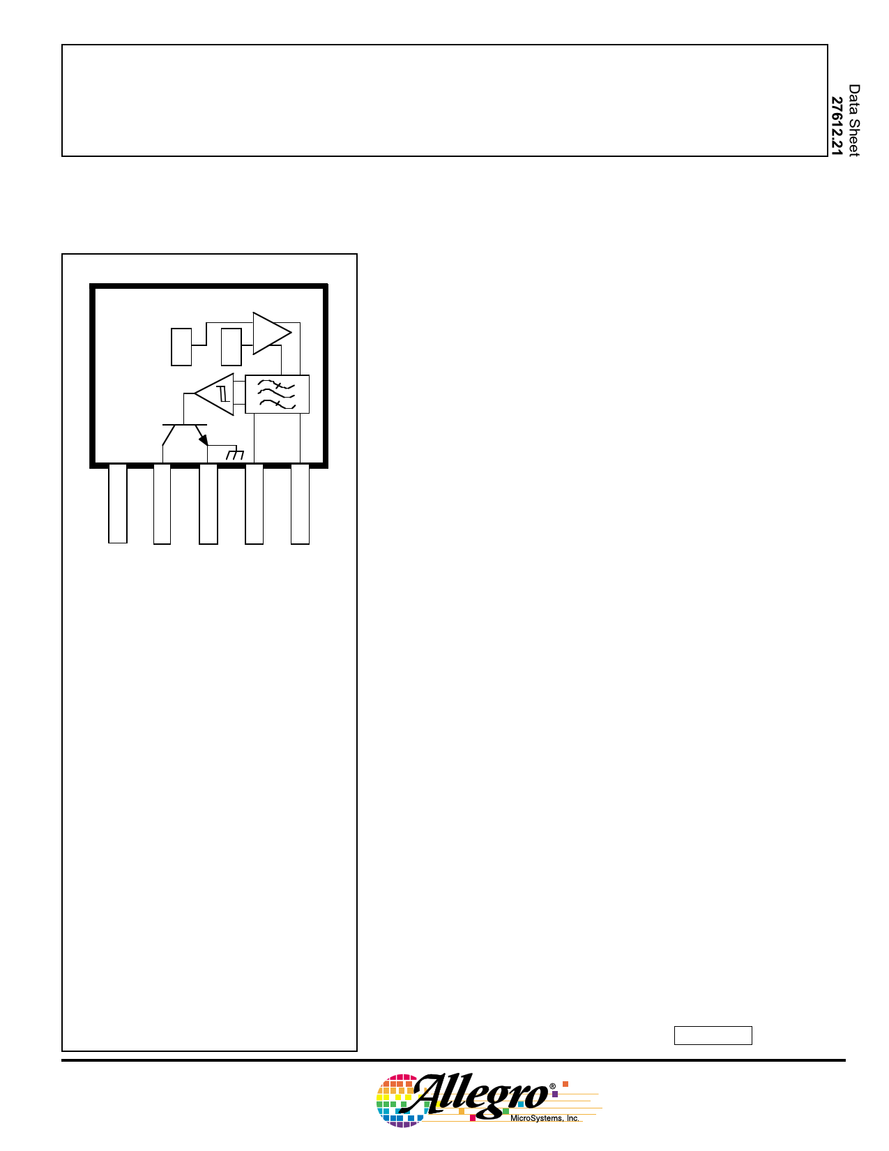
HALL-EFFECT GEAR-TOOTH SENSOR
—AC COUPLED
XX
VCC
12 34 5
Dwg. PH-011-1
Pinning is shown viewed from branded side.
ABSOLUTE MAXIMUM RATINGS
at TA = +25°C
Supply Voltage, VCC ............................. 24 V
Reverse Battery Voltage, VRCC .......... -30 V
Magnetic Flux Density, B ............ Unlimited
Output Off Voltage, VOUT ...................... 24 V
Output Current, IOUT ......................... 25 mA
Package Power Dissipation,
PD ............................................ 500 mW
Operating Temperature Range,
TA ............................... -40°C to +150°C
Storage Temperature Range,
TS ............................... -65°C to +170°C
The A3064LKA ac-coupled Hall-effect gear-tooth sensor is a
monolithic integrated circuit that switches in response to changing
differential magnetic fields created by moving ferrous targets. This
device is ideal for use in non-zero-speed, gear-tooth-based speed,
position, and timing applications such as in anti-lock braking systems,
transmissions, and crankshafts.
When coupled with a back-biasing magnet, the sensor can be
configured to turn on or off with the leading or trailing edge of a gear-
tooth or slot. Changes in fields on the magnet face caused by a moving
ferrous mass are sensed by two integrated Hall transducers and are
differentially amplified by on-chip electronics. This differential
sensing design provides immunity to radial vibration within the
device’s operating air gap. Steady-state magnet and system offsets are
eliminated using an on-chip differential band-pass filter. This filter
also provides relative immunity to interference from RF and electro-
magnetic sources. The on-chip temperature compensation and Schmitt
trigger circuitry minimizes shifts in effective working air gaps and
switch points over temperature, allowing operation to low frequencies
over a wide range of air gaps and temperatures.
Each Hall-effect digital Integrated circuit includes a voltage
regulator, two quadratic Hall-effect sensing elements, temperature
compensating circuitry, a low-level amplifier, band-pass filter, Schmitt
trigger, and an open-collector output driver. The on-board regulator
permits operation with supply voltages of 4.5 to 24 volts. The output
stage can easily switch 20 mA over the full frequency response range
of the sensor and is compatible with bipolar and MOS logic circuits.
The device is packaged in a 5-pin plastic SIP.
FEATURES
s Senses Motion of Ferrous Targets
s Wide Operating Temperature Range
s Operation to 30 kHz
s Resistant to EMI
s Large Effective Air Gap
s 4.5 V to 24 V Operation
s Output Compatible With All Logic Families
s Reverse Battery Protection
s Resistant to Physical Stress
Always order by complete part number, e.g., A3064LKA .
1 page 
3064
HALL-EFFECT
GEAR-TOOTH SENSOR
—AC COUPLED
APPLICATIONS INFORMATION (cont’d)
low) when BE1 - BE2 < BRP. The difference between BOP and
BRP is the hysteresis of the device.
Note that powering up in the absence of a differential
magnetic field (less than the device BOP and higher than the
device BRP) will allow an indeterminate output state. The
correct output state is warranted after the first excursion beyond
BOP or BRP.
Figure 2 relates the output state of a back-biased sensor IC,
with switching characteristics shown in Figure 1, to the target
gear profile and position. Assume a north pole back-bias
configuration (equivalent to a south pole at the face of the
device). The motion of the gear produces a phase-shifted field
at E1 and E2 (Figure 2(a)); internal conditioning circuitry
subtracts the fields at the two elements (Figure 2(b)); this
differential field is band-pass filtered to remove dc offset
components and then fed into a Schmitt trigger; the Schmitt
trigger switches the output transistor at the thresholds BOP and
BRP. As shown (Figure 2(c)), the IC output is low whenever
sensor E2 faces a (ferrous) gear tooth and sensor E1 faces air.
The output is high when sensor E1 faces air and sensor E2 faces
a ferrous target.
AC-Coupled Operation. Steady-state magnet and
system offsets are eliminated using an on-chip differential band-
pass filter. The lower frequency cut-off of this patented filter is
set using an external capacitor, the value of which can range
from 0.01 µF to 10 µF. The high-frequency cut-off of this filter
is set at 30 kHz by an internal integrated capacitor.
The differential structure of this filter improves the ability
of the IC to reject single-ended noise on the ground or supply
line and, as a result, makes it more resistant to radio-frequency
and electromagnetic interference typically seen in hostile
remote-sensing environments. This filter configuration also
increases system tolerance to capacitor degradation at high
temperatures, allowing the use of an inexpensive external
ceramic capacitor.
Low-Frequency Operation. Low-frequency operation
of the sensor is set by the value of an external capacitor.
Ideally, the differential flux density range (determined by the
applied target) vs. air gap assumes a perfect sinusoidal input.
Figure 3 provides the low-frequency cut-off (-3 dB point) of the
filter as a function of capacitance value. This information
should be used with care. In reality, when used with gear teeth,
4300 G
B &B
E1 E2
4150 G
150 G
BOP= +15 G
B –B
E1 E2
0G
BRP= 0 G
-150 G
V
OUT
V
OUT(SAT)
1k
100
10
1.0
0.1
0.01
Figure 2
LEADING
EDGE
TRAILING
EDGE
GEAR
DIRECTION
OF ROTATION
E2 E1
NORTH
SOUTH
(a)
(b)
OUTPUT DUTY CYCLE ≈ 50%
Figure 3
(c)
Dwg. WH-003-3
0.1 1.0
CAPACITANCE IN µF
10
Dwg. GH-025
www.allegromicro.com
5
5 Page | ||
| Páginas | Total 8 Páginas | |
| PDF Descargar | [ Datasheet A3064.PDF ] | |
Hoja de datos destacado
| Número de pieza | Descripción | Fabricantes |
| A306 | Triode | Philips |
| A3064 | HALL-EFFECT GEAR-TOOTH SENSOR | Allegro MicroSystems |
| A3064 | R.F. PENTODE | ETC |
| A3064 | R.F. Pentode | GEC |
| Número de pieza | Descripción | Fabricantes |
| SLA6805M | High Voltage 3 phase Motor Driver IC. |
Sanken |
| SDC1742 | 12- and 14-Bit Hybrid Synchro / Resolver-to-Digital Converters. |
Analog Devices |
|
DataSheet.es es una pagina web que funciona como un repositorio de manuales o hoja de datos de muchos de los productos más populares, |
| DataSheet.es | 2020 | Privacy Policy | Contacto | Buscar |