|
|
|
PDF QT118H-S Data sheet ( Hoja de datos )
| Número de pieza | QT118H-S | |
| Descripción | CHARGE-TRANSFER TOUCH SENSOR | |
| Fabricantes | ETC | |
| Logotipo | ||
Hay una vista previa y un enlace de descarga de QT118H-S (archivo pdf) en la parte inferior de esta página. Total 13 Páginas | ||
|
No Preview Available !
lQ
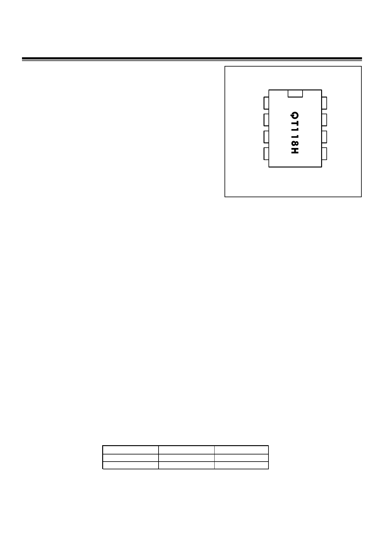
QProx™ QT118H
CHARGE-TRANSFER TOUCH SENSOR
Less expensive than many mechanical switches
Projects a ‘touch button’ through any dielectric
Turns small objects into intrinsic touch sensors
100% autocal for life - no adjustments required
Only one external part required - a 1¢ capacitor
Piezo sounder direct drive for ‘tactile’ click feedback
LED drive for visual feedback
3V 20µA single supply operation
Toggle mode for on/off control (strap option)
10s or 60s auto-recalibration timeout (strap option)
Pulse output mode (strap option)
Gain settings in 3 discrete levels
Simple 2-wire operation possible
HeartBeat™ health indicator on output
Vdd
Out
O pt1
O pt2
1
2
3
4
8 Vss
7 Sns2
6 Sns1
5 Gain
APPLICATIONS -
Light switches
Industrial panels
Appliance control
Security systems
Access systems
Pointing devices
Elevator buttons
Toys & games
The QT118H charge-transfer (“QT’”) touch sensor is a self-contained digital IC capable of detecting near-proximity or touch. It will
project a sense field through almost any dielectric, like glass, plastic, stone, ceramic, and most kinds of wood. It can also turn
small metal-bearing objects into intrinsic sensors, making them respond to proximity or touch. This capability coupled with its
ability to self calibrate continuously can lead to entirely new product concepts.
It is designed specifically for human interfaces, like control panels, appliances, toys, lighting controls, or anywhere a mechanical
switch or button may be found; it may also be used for some material sensing and control applications provided that the presence
duration of objects does not exceed the recalibration timeout interval.
The IC requires only a common inexpensive capacitor in order to function. A bare piezo beeper can be connected to create a
‘tactile’ feedback clicking sound; the beeper itself then doubles as the required external capacitor, and it can also become the
sensing electrode. An LED can also be added to provide visual sensing indication. With a second inexpensive capacitor the device
can operated in 2-wire mode, where both power and signal traverse the same wire pair to a host. This mode allows the sensor to
be wired to a controller with only a twisted pair over a long distances.
Power consumption is under 20µA in most applications, allowing operation from Lithium cells for many years. In most cases the
power supply need only be minimally regulated.
The IC’s RISC core employs signal processing techniques pioneered by Quantum; these are specifically designed to make the
device survive real-world challenges, such as ‘stuck sensor’ conditions and signal drift. Even sensitivity is digitally determined and
remains constant in the face of large variations in sample capacitor Cs and electrode Cx. No external switches, opamps, or other
analog components aside from Cs are usually required.
The device includes several user-selectable built in features. One, toggle mode, permits on/off touch control, for example for light
switch replacement. Another makes the sensor output a pulse instead of a DC level, which allows the device to 'talk' over the
power rail, permitting a simple 2-wire interface. The Quantum-pioneered HeartBeat™ signal is also included, allowing a host
controller to monitor the health of the QT118H continuously if desired. By using the charge transfer principle, the IC delivers a
level of performance clearly superior to older technologies in a highly cost-effective package.
lq
AVAILABLE OPTIONS
TA
00C to +700C
-400C to +850C
SOIC
QT118H-S
QT118H-IS
8-PIN DIP
QT118H-D
-
©1999-2000 Quantum Research Group
R1.03 / 0302
1 page 
2 - QT118H SPECIFICS
2.1 SIGNAL PROCESSING
The QT118H processes all signals using 16 bit precision,
using a number of algorithms pioneered by Quantum. The
algorithms are specifically designed to provide for high
survivability in the face of all kinds of adverse environmental
changes.
2.1.1 DRIFT COMPENSATION ALGORITHM
Signal drift can occur because of changes in Cx and Cs over
time. It is crucial that drift be compensated for, otherwise
false detections, non-detections, and sensitivity shifts will
follow.
Drift compensation (Figure 2-1) is performed by making the
reference level track the raw signal at a slow rate, but only
while there is no detection in effect. The rate of adjustment
must be performed slowly, otherwise legitimate detections
could be ignored. The QT118H drift compensates using a
slew-rate limited change to the reference level; the threshold
and hysteresis values are slaved to this reference.
Once an object is sensed, the drift compensation
mechanism ceases since the signal is legitimately high, and
therefore should not cause the reference level to change.
The QT118H's drift compensation is 'asymmetric': the
reference level drift-compensates in one direction faster than
it does in the other. Specifically, it compensates faster for
decreasing signals than for increasing signals. Increasing
signals should not be compensated for quickly, since an
approaching finger could be compensated for partially or
entirely before even touching the sense pad. However, an
obstruction over the sense pad, for which the sensor has
already made full allowance for, could suddenly be removed
leaving the sensor with an artificially elevated reference level
and thus become insensitive to touch. In this latter case, the
sensor will compensate for the object's removal very quickly,
usually in only a few seconds.
2.1.2 THRESHOLD CALCULATION
Unlike the QT110 device, the internal threshold level is fixed
at one of two setting as determined by Table 1-1. These
setting are fixed with respect to the internal reference level,
which in turn can move in accordance with the drift
compensation mechanism..
The QT118H employs a hysteresis dropout below the
threshold level of 17% of the delta between the reference
and threshold levels.
2.1.3 MAX ON-DURATION
If an object or material obstructs the sense pad the signal
may rise enough to create a detection, preventing further
operation. To prevent this, the sensor includes a timer which
monitors detections. If a detection exceeds the timer setting,
the timer causes the sensor to perform a full recalibration.
This is known as the Max On-Duration feature.
After the Max On-Duration interval, the sensor will once
again function normally, even if partially or fully obstructed,
to the best of its ability given electrode conditions. There are
two timeout durations available via strap option: 10 and 60
seconds.
Table 2-1 Output Mode Strap Options
Tie
Pin 3 to:
Tie
Pin 4 to:
Max On-
Duration
DC Out
Vdd
Vdd
10s
DC Out
Vdd
Gnd
60s
Toggle
Gnd
Gnd
10s
Pulse
Gnd
Vdd
10s
2.1.4 DETECTION INTEGRATOR
It is desirable to suppress detections generated by electrical
noise or from quick brushes with an object. To accomplish
this, the QT118H incorporates a detect integration counter
that increments with each detection until a limit is reached,
after which the output is activated. If no detection is sensed
prior to the final count, the counter is reset immediately to
zero. The required count is 4.
The Detection Integrator can also be viewed as a 'consensus'
filter, that requires four detections in four successive bursts
to create an output. As the basic burst spacing is 75ms, if
this spacing was maintained throughout all 4 counts the
sensor would react very slowly. In the QT118H, after an
initial detection is sensed, the remaining three bursts are
spaced about 18ms apart, so that the slowest reaction time
possible is 75+18+18+18 or 129ms and the fastest possible
is 54ms, depending on where in the initial burst interval the
contact first occurred. The response time will thus average
92ms.
Figure 2-2 Powering From a CMOS Port Pin
PORT X.m
CMOS
m ic ro c o n tr o lle r
PORT X.n
OUT
0.01µ F
Vdd
Q T11 8
V ss
2.1.5 FORCED SENSOR RECALIBRATION
The QT118H has no recalibration pin; a forced recalibration
is accomplished only when the device is powered up.
However, the supply drain is so low it is a simple matter to
treat the entire IC as a controllable load; simply driving the
QT118H's Vdd pin directly from another logic gate or a
microprocessor port (Figure 2-2) will serve as both power
and 'forced recal'. The source resistance of most CMOS
gates and microprocessors is low enough to provide direct
power without any problems. Note that most 8051-based
microcontrollers have only a weak pullup drive capability
and will require true CMOS buffering. Any 74HC or 74AC
series gate can directly power the QT118H, as can most
other microcontrollers. A 0.01uF minimum bypass capacitor
close to the device is essential; without it the device can
lq
4
5 Page 
4.5 DC SPECIFICATIONS
Vdd = 3.0V, Cs = 10nF, Cx = 5pF, TA = recommended range, unless otherwise noted
Parameter
Description
Min Typ Max Units
Notes
VDD Supply voltage 2.45 5.25 V
IDD Supply current
20 µA
VDDS
Supply turn-on slope
100
V/s Required for proper startup
VIL Low input logic level
0.8 V OPT1, OPT2
VHL High input logic level
2.2
V OPT1, OPT2
VOL Low output voltage
0.6 V OUT, 4mA sink
VOH High output voltage
Vdd-0.7
V OUT, 1mA source
IIL Input leakage current
±1 µA OPT1, OPT2
CX Load capacitance range
0
100 pF
IX Min shunt resistance
500K
✡ Resistance from SNS1 to SNS2
AR Acquisition resolution
14 bits
S Sensitivity range
1,000
28 fF Note 2
Preliminary Data: All specifications subject to change.
Figure 4-1 - Typical Threshold Sensitivity vs. Cx,
High Gain, at Selected Values of Cs; Vdd = 3.0
10.00
1.00
0.10
10nF
20nF
50nF
100nF
200nF
500nF
0.01
0
10 20 30
Cx Load, pF
40
Figure 4-2 - Typical Threshold Sensitivity vs. Cx,
Medium Gain, Selected Values of Cs; Vdd = 3.0
10.00
1.00
0.10
10nF
20nF
50nF
100nF
200nF
500nF
0.01
0
10 20 30
Cx Load, pF
40
lq
10
11 Page | ||
| Páginas | Total 13 Páginas | |
| PDF Descargar | [ Datasheet QT118H-S.PDF ] | |
Hoja de datos destacado
| Número de pieza | Descripción | Fabricantes |
| QT118H-D | CHARGE-TRANSFER TOUCH SENSOR | ETC |
| QT118H-IS | CHARGE-TRANSFER TOUCH SENSOR | ETC |
| QT118H-S | CHARGE-TRANSFER TOUCH SENSOR | ETC |
| Número de pieza | Descripción | Fabricantes |
| SLA6805M | High Voltage 3 phase Motor Driver IC. |
Sanken |
| SDC1742 | 12- and 14-Bit Hybrid Synchro / Resolver-to-Digital Converters. |
Analog Devices |
|
DataSheet.es es una pagina web que funciona como un repositorio de manuales o hoja de datos de muchos de los productos más populares, |
| DataSheet.es | 2020 | Privacy Policy | Contacto | Buscar |