|
|
|
PDF US1175CP Data sheet ( Hoja de datos )
| Número de pieza | US1175CP | |
| Descripción | 7.5A ULTRA LOW DROPOUT POSITIVE ADJUSTABLE REGULATOR | |
| Fabricantes | UNISEM | |
| Logotipo | ||
Hay una vista previa y un enlace de descarga de US1175CP (archivo pdf) en la parte inferior de esta página. Total 5 Páginas | ||
|
No Preview Available !
US1175
FEATURES
7.5A ULTRA LOW DROPOUT POSITIVE
ADJUSTABLE REGULATOR
PRELIMINARY DATASHEET
DESCRIPTION
0.5V Dropout at 7.5A (Equivalent of 67mΩ)
Fast Transient Response
1% Voltage Reference Initial Accuracy
Built-in Thermal Shutdown
APPLICATIONS
3.3V to 2.7V Intel I740 chip set.
The US1175 product is a 7.5A regulator with extremely
low dropout voltage using a proprietary Bipolar pro-
cess that achieves comparable equivalent on re-
sistance to that of discrete MOSFETs. This product is
specifically designed to provide well regulated supply for
applications requiring very low dropout such as
2.8V from 3.3V ATX power supplies where the same
efficiency as the switcher can be achieved without
the cost and complexity associated with switching
regulators. One such application is the new graphic
chip sets that requires 2.7V supply such as the Intel
I740 chip set.
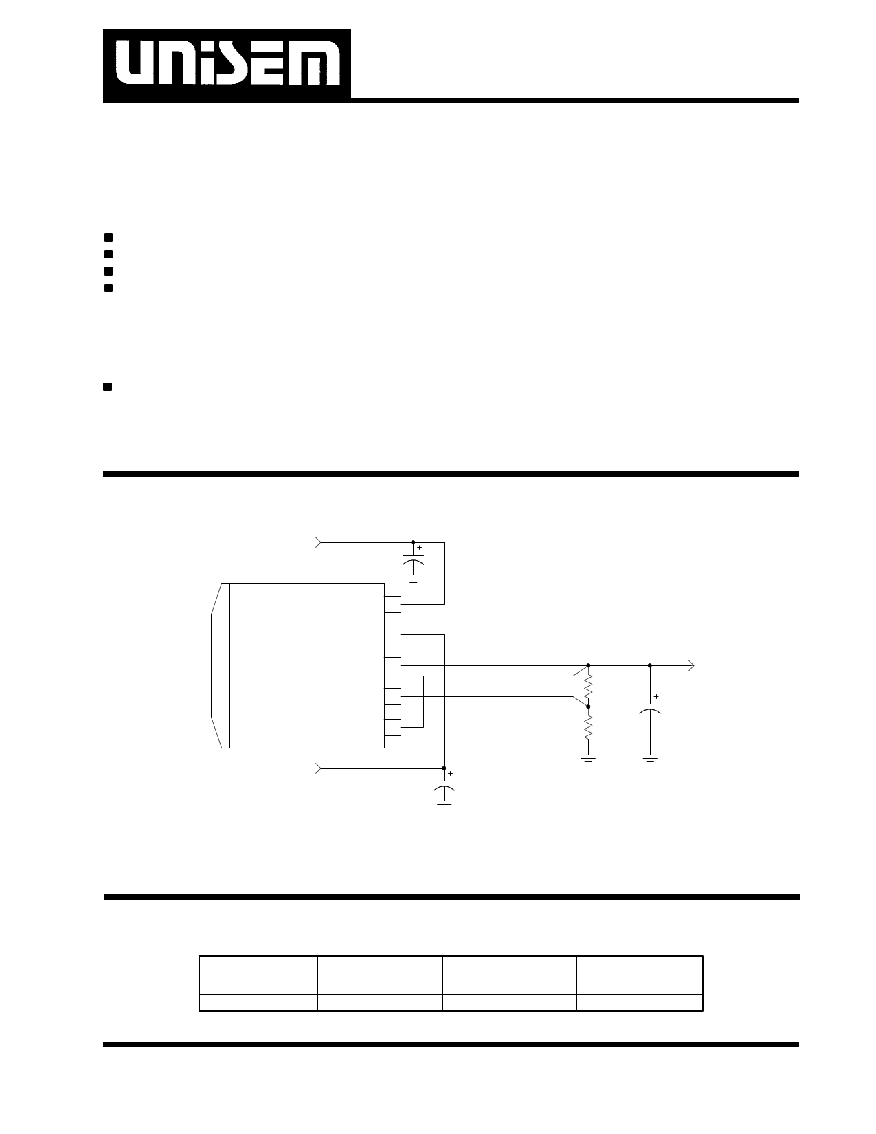
TYPICAL APPLICATION
3.3V
C1
Vin 5
US1175
Vctrl 4
Vout 3
Adj 2
Vsense 1
1175app1-1.0
5V
C2
2.7V
R1
C3
R2
Typical application of US1175 .
PACKAGE ORDER INFORMATION
Tj (°C)
0 TO 125
5 PIN PLASTIC 5 PIN PLASTIC 8 PIN PLASTIC
TO263 (M) POWER FLEX (P) SOIC (S)
US1175CM
US1175CP
US1175CS
Rev. 1.2
11/29/99
2-1
1 page 
US1175
The US1175 keeps a constant 1.25V between the Vsense
pin and the Vadj pin. By placing a resistor R1 across
these two pins and connecting the Vsense and Vout pin
together , a constant current flows through R1, adding
to the Iadj current and into the R2 resistor producing a
voltage equal to the (1.25/R1)*R2 + Iadj*R2 .This voltage
is then added to the 1.25V to set the output voltage.
This is summarized in the above equation. Since the
minimum load current requirement of the US1175 is 10
mA , R1 is typically selected to be a 121Ω resistor so
that it automatically satisfies this condition. Notice that
since the Iadj is typically in the range of 50uA it only
adds a small error to the output voltage and should be
considered when very precise output voltage setting is
required.
Load Regulation
Since the US1175 has separate pins for the output (Vout)
and the sense (Vsense), it is ideal for providing true re-
mote sensing of the output voltage at the load.This
means that the voltage drops due to parasitic resistance
such as PCB traces between the regulator and the load
are compensated for using remote sensing. Figure 3
shows a typical application of the US1175 with remote
sensing.
Vin
Vctrl
Vin Vout
US1175
Vctrl Vsense
Adj
1175app3-1.0
R1
R2
RL
For most applications a minimum of 100uF aluminum
electrolytic capacitor such as Sanyo, MVGX series
,Panasonic FA series as well as the Nichicon PL series
insures both stability and good transient response.
Thermal Design
The US1175 incorporates an internal thermal shutdown
that protects the device when the junction temperature
exceeds the allowable maximum junction temperature.
Although this device can operate with junction tempera-
tures in the range of 150°C ,it is recommended that the
selected heat sink be chosen such that during maxi-
mum continuos load operation the junction temperature
is kept below this number. The example below shows
the steps in selecting the proper surface mount pack-
age.
Assuming, the following conditions:
Vout=2.7V
Vin=3.3V
Vctrl=5V
Iout=2A DC Avg
Calculate the maximum power dissipation using the fol-
lowing equation:
Pd=Iout*(Vin-Vout) + (Iout/60)*(Vctrl - Vout)
Pd=2*(3.3-2.7) + (2/60)*(5-2.7)=1.28 W
Using table below select the proper package and the
amount of copper board needed.
Pkg Copper θJA(°C/W)
Area
TO263 1.4"X1.4" 25
TO263 1.0"X1.0" 30
TO263 0.7"X0.7" 35
TO263 Pad Size 45
SO8 1.0"X1.0" 55
Max Pd
(Ta=25°C)
4.4W
3.7W
3.1W
2.4W
2.0W
Max Pd
(Ta=45°C)
3.6W
3.0W
2.6W
2.0W
1.63W
Figure 3 - Schematic showing connection for best
load regulation
Stability
The US1175 requires the use of an output capacitor as
part of the frequency compensation in order to make the
regulator stable. Typical designs for the microproces-
sor applications use standard electrolytic capacitors with
typical ESR in the range of 50 to 100 mΩ and an output
capacitance of 500 to 1000uF. Fortunately as the ca-
pacitance increases, the ESR decreases resulting in a
fixed RC time constant. The US1175 takes advantage of
this phenomena in making the overall regulator loop
stable.
Note: Above table is based on the maximum junction
temperature of 135°C.
As shown in the above table, any of the two packages
will do the job. For low cost applications the SO8 pack-
age is recommended.
Rev. 1.2
11/29/99
2-5
5 Page | ||
| Páginas | Total 5 Páginas | |
| PDF Descargar | [ Datasheet US1175CP.PDF ] | |
Hoja de datos destacado
| Número de pieza | Descripción | Fabricantes |
| US1175CM | 7.5A ULTRA LOW DROPOUT POSITIVE ADJUSTABLE REGULATOR | UNISEM |
| US1175CP | 7.5A ULTRA LOW DROPOUT POSITIVE ADJUSTABLE REGULATOR | UNISEM |
| US1175CS | 7.5A ULTRA LOW DROPOUT POSITIVE ADJUSTABLE REGULATOR | UNISEM |
| Número de pieza | Descripción | Fabricantes |
| SLA6805M | High Voltage 3 phase Motor Driver IC. |
Sanken |
| SDC1742 | 12- and 14-Bit Hybrid Synchro / Resolver-to-Digital Converters. |
Analog Devices |
|
DataSheet.es es una pagina web que funciona como un repositorio de manuales o hoja de datos de muchos de los productos más populares, |
| DataSheet.es | 2020 | Privacy Policy | Contacto | Buscar |