|
|
|
PDF 74AHCT594 Data sheet ( Hoja de datos )
| Número de pieza | 74AHCT594 | |
| Descripción | 8-BIT SHIFT REGISTER | |
| Fabricantes | Diodes | |
| Logotipo | ||
Hay una vista previa y un enlace de descarga de 74AHCT594 (archivo pdf) en la parte inferior de esta página. Total 10 Páginas | ||
|
No Preview Available !
74AHCT594
8-BIT SHIFT REGISTER WITH 8-BIT OUTPUT REGISTER
Description
The 74AHCT594 is an advanced high speed CMOS device that is
designed to be pin compatable with 74LS low power Schottky types.
An eight bit shift register accepts data from the serial input (DS) on
each positive transition of the shift register clock (SHCP). When
asserted low the shift register reset function (SHR) sets all shift
register values to zero and is independent of all clocks. Also when
asserted low, the storage register reset function (STR) sets all shift
register values to zero and is independent of all clocks.
Data from the input serial shift register is placed in the output register
with a rising pulse on the storages resister clock (STCP). The
storage resister includes output Q7S which is used for cascading
information between devices. As the information moves into the
storage register, it is asserted on the push-pull outputs Q0-Q7.
All registers capture data on rising edge and change output on the
falling edge. If both clocks are connected together, the input shift
register is always one clock cycle ahead of the output register.
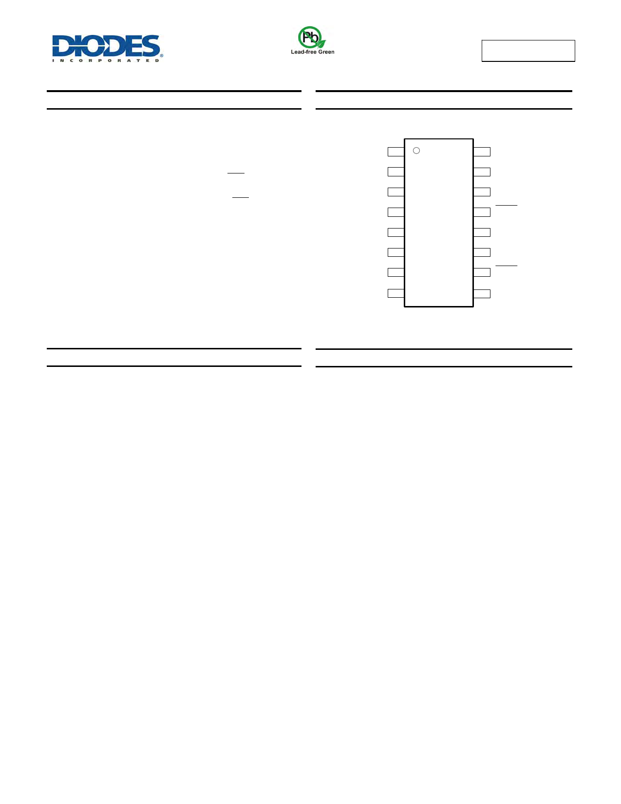
Pin Assignments
Q1
Q2
Q3
Q4
Q5
Q6
Q7
GND
( Top View )
1 16
2 15
3 14
4 13
5 12
6 11
7 10
89
Vcc
Q0
DS
STR
STCP
SHCP
SHR
Q7S
SO-16 / TSSOP-16
Features
Wide Supply Voltage Range from 4.5V to 5.5V
Sinks or sources 8mA at VCC = 4.5V
CMOS low power consumption
Schmitt Trigger Action at All Inputs
Inputs accept up to 6.0V
ESD Protection Tested per JESD 22
Exceeds 200-V Machine Model (A115-A)
Exceeds 2000-V Human Body Model (A114-A)
Exceeds 1000-V Charged Device Model (C101C)
Latch-Up Exceeds 250mA per JESD 78, Class II
Totally Lead-Free & Fully RoHS Compliant (Notes 1 & 2)
Halogen and Antimony Free. “Green” Device (Note 3)
Applications
General Purpose Logic
Serial to Parallel Data conversion
Capture and hold data for extended periods of time.
Allow simple serial bit streams from a microcontroller to control as
many peripheral lines as needed.
Wide array of products such as:
Computer Peripherals
Appliances
Industrial control
Notes:
1. No purposely added lead. Fully EU Directive 2002/95/EC (RoHS) & 2011/65/EU (RoHS 2) compliant.
2. See http://www.diodes.com/quality/lead_free.html for more information about Diodes Incorporated’s definitions of Halogen- and Antimony-free, "Green"
and Lead-free.
3. Halogen- and Antimony-free "Green” products are defined as those which contain <900ppm bromine, <900ppm chlorine (<1500ppm total Br + Cl) and
<1000ppm antimony compounds.
Click here for ordering information, located at the end of datasheet
74AHCT594
Document number: DS35485 Rev. 2 - 2
1 of 10
www.diodes.com
June 2013
© Diodes Incorporated
1 page 
74AHCT594
Switching Characteristics
Symbol /
Parameter
Pins
Test Conditions
VCC
fMAX
Maximum
Frequency
tW
Pulse Width
tSU
Set-up Time
tH
Hold Time
SHCP or
STCP
Figure 2 CL = 15pF 4.5V to 5.0V
SHCP
HIGH or LOW
Figure 2 CL = 50pF
4.5V to 5.0V
STCP
HIGH or LOW
Figure 2 CL = 50pF
4.5V to 5.0V
SHR and STR
HIGH or LOW
Figure 2 CL = 50pF
4.5V to 5.0V
DS to SHCP
SHR to STCP
SHCP to
STCP
Figure 2 CL = 50pF
Figure 2 CL = 50pF
Figure 2 CL = 50pF
4.5V to 5.0V
4.5V to 5.0V
4.5V to 5.0V
DS to SHCP Figure 2 CL = 50pF 4.5V to 5.0V
tREC
Recovery Time
SHR to SHCP
and STR to
Figure 2 CL = 50pF
4.5V to 5.0V
STCP
tPLH
Propagation
Delay
SHCP toQ7S
STCP to Qn
Figure 2 CL = 15pF 4.5V to 5.0V
Figure 2 CL = 50pF 4.5V to 5.0V
Figure 2 CL = 15pF 4.5V to 5.0V
Figure 2 CL = 50pF 4.5V to 5.0V
SHCP to Q7S Figure 2 CL = 15pF 4.5V to 5.0V
Figure 2 CL = 50pF 4.5V to 5.0V
tPHl
Propagation
Delay
STCP to Qn
SHR to Q7S
Figure 2 CL = 15pF
Figure 2 CL = 50pF
Figure 2 CL = 15pF
Figure 2 CL = 50pF
4.5V to 5.0V
4.5V to 5.0V
4.5V to 5.0V
4.5V to 5.0V
Figure 2 CL = 15pF 4.5V to 5.0V
STR to Qn
Figure 2 CL = 50pF 4.5V to 5.0V
TA = +25°C
Min Typ Max
90 160
5.5
5.5
5.2
3.0
5.0
5.0
5 2.0
10 2.9
4.1 6.7
5.4 8.8
3.7 6.1
5.2 8.5
4.1 6.7
5.4 8.8
3.7 6.1
5.2 8.5
4.3 7.0
5.4 8.8
4.5 7.4
5.7 9.4
-40°C to +85°C
Min Max
80
6.0
6.0
5.5
3.0
5.0
5.0
2.0
3.3
1.8 7.6
2.4 10.1
1.9 6.9
2.6 9.7
1.8 7.6
2.4 10.1
1.9 6.9
2.6 9.7
2.4 8.0
2.7 10.1
2.3 8.4
3.1 10.7
-40°C to +125°C
Unit
Min Max
70 MHz
6.5
6.5 ns
6.0
3.5
5.5 ns
5.5
2.5 ns
3.8 ns
1.8 8.3
2.4 11.0
ns
1.9 7.2
2.6 10.5
1.8 8.3
2.4 11.0
ns
1.9 7.2
2.6 10.5
2.4 8.7
ns
2.7 11.0
2.3 9.2
ns
3.1 11.7
Operating Characteristics (@TA = +25°C, unless otherwise specified.)
Parameter
Test
Conditions
VCC = 5V
Typ
Cpd
Power dissipation
capacitance
f = 1 MHz all outputs switching-no load
VI = GND TO VCC -1.5V
51
Unit
pF
74AHCT594
Document number: DS35485 Rev. 2 - 2
5 of 10
www.diodes.com
June 2013
© Diodes Incorporated
5 Page | ||
| Páginas | Total 10 Páginas | |
| PDF Descargar | [ Datasheet 74AHCT594.PDF ] | |
Hoja de datos destacado
| Número de pieza | Descripción | Fabricantes |
| 74AHCT594 | 8-bit shift register | NXP Semiconductors |
| 74AHCT594 | 8-BIT SHIFT REGISTER | Diodes |
| 74AHCT595 | 8-bit serial-in/serial or parallel-out shift register with output latches; 3-state | NXP Semiconductors |
| 74AHCT595 | 8-BIT SHIFT REGISTER 8-BIT OUTPUT REGISTER | Diodes |
| Número de pieza | Descripción | Fabricantes |
| SLA6805M | High Voltage 3 phase Motor Driver IC. |
Sanken |
| SDC1742 | 12- and 14-Bit Hybrid Synchro / Resolver-to-Digital Converters. |
Analog Devices |
|
DataSheet.es es una pagina web que funciona como un repositorio de manuales o hoja de datos de muchos de los productos más populares, |
| DataSheet.es | 2020 | Privacy Policy | Contacto | Buscar |