|
|
|
PDF MBR10200C Data sheet ( Hoja de datos )
| Número de pieza | MBR10200C | |
| Descripción | HIGH VOLTAGE POWER SCHOTTKY RECTIFIER | |
| Fabricantes | Diodes | |
| Logotipo | ||
Hay una vista previa y un enlace de descarga de MBR10200C (archivo pdf) en la parte inferior de esta página. Total 12 Páginas | ||
|
No Preview Available !
MBR10200C
HIGH VOLTAGE POWER SCHOTTKY RECTIFIER
Product Summary
VRRM (V)
200
IO (A)
2x5
VF (MAX) (V)
@ +25°C
0.95
IR (MAX) (mA)
@ +25°C
0.15
Description
High voltage dual Schottky rectifier suited for switch mode power
supplies and other power converters. This device is intended for use
in medium voltage operation, and particularly, in high frequency
circuits where low switching losses and low noise are required.
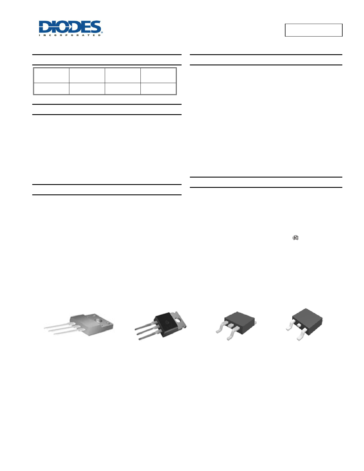
MBR10200C is available in TO-220-3 (2), TO-220F-3 (Option 1), TO-
263-2 and TO-252-2 (1) packages.
Features
Low Forward Voltage: 0.95V @ +25C
High Surge Capacity
+150C Operating Junction Temperature
10A Total (5A Per Diode Leg)
Guard-Ring for Stress Protection
Pb-free Package
TO-220-3 (2) ,TO-220F-3 (Option 1), TO-252-2 (1) and TO-263-2
Lead-Free Finish; RoHS Compliant (Notes 1 & 2)
Available in “Green” Packages: TO-220-3 (2) and TO-220F-3
(Option 1), TO-252-2 (1) and TO-263-2
Lead-Free Finish; RoHS Compliant (Notes 1 & 2)
Halogen and Antimony Free. “Green” Device (Note 3)
Applications
Power Supply Output Rectification
Power Management
Instrumentation
Mechanical Data
Case: TO-220-3 (2), TO-220F-3 (Option 1), TO-252-2 (1) and TO-
263-2
Case Material: Molded Plastic, “Green” Molding Compound. UL
Flammability Classification Rating 94V-0
Moisture Sensitivity: Level 1 per J-STD-020
Terminals: Finish - Matte Tin Annealed over Copper Leadframe.
Solderable per MIL-STD-202, Method 208
Polarity: See Below
Weight:
TO-220-3 (2) – 1.95 grams (Approximate)
TO-220F-3 (Option 1) – 1.69 grams (Approximate)
TO-263-2 – 1.9 grams (Approximate)
TO-252-2 (1) – 0.31 grams (Approximate)
TO-220F-3 (Option 1)
TO-220-3 (2)
TO-263-2
TO-252-2 (1)
Notes:
1. EU Directive 2002/95/EC (RoHS) & 2011/65/EU (RoHS 2) compliant. All applicable RoHS exemptions applied.
2. See http://www.diodes.com/quality/lead_free.html for more information about Diodes Incorporated’s definitions of Halogen- and Antimony-free, "Green"
and Lead-free.
3. Halogen- and Antimony-free "Green” products are defined as those which contain <900ppm bromine, <900ppm chlorine (<1500ppm total Br + Cl) and
<1000ppm antimony compounds.
MBR10200C
Document number: DS36952 Rev. 4 - 2
1 of 12
www.diodes.com
July 2015
© Diodes Incorporated
1 page 
MBR10200C
Thermal Characteristics
Characteristic
Symbol
Rating
TO-220-3 (2)
Maximum Thermal Resistance (Junction to Case)
(Note 7)
RθJC
TO-220F-3 (Option 1)
TO-252-2 (1)
TO-263-2
TO-220-3 (2)
Maximum Thermal Resistance (Junction to Ambient)
(Note 7)
RθJA
TO-220F-3 (Option 1)
TO-252-2 (1)
TO-263-2
Note 7: Device mounted on heat sink, with minimum recommended pad layout per http://www.diodes.com.
3.0
4.5
2.0
2.0
60
60
50
50
Unit
oC/W
oC/W
Electrical Characteristics (Each Diode Leg)
Characteristic
Symbol
Rating
Unit
Test Condition
Maximum Instantaneous Forward Voltage Drop
(Note 8)
0.95
VF 0.85
IF = 5A, TC = +25C
V
IF = 5A, TC = +125C
0.15 Rated DC Voltage, TC = +25C
Maximum Instantaneous Reverse Current (Note 8)
IR
15
mA
Rated DC Voltage, TC = +125C
Note 8: Short duration pulse test used to minimize self-heating effect, Pulse Test Width = 300µs, Duty Cycle < 2.0%.
100
1000
100
10
10
11
0.1 25C
125C
150C
0.01
0.1 0.2 0.3 0.4 0.5 0.6 0.7 0.8 0.9 1.0 1.1 1.2
Forward Voltage (V)
Figure 1. Typical Forward Voltage Per Diode
0.1
25C
0.01 125C
150C
1E-3
0
50 100 150
Reverse Voltage (V)
200
Figure 2. Typical Reverse Current Per Diode
10
9
8
Note 7
7
6
5
4
3
2
1
0
100 105 110 115 120 125 130 135 140 145 150 155 160
T , Case Temperature (oC)
C
Figure 3. Average Rectified Forward Current vs.
Case Temperature (Per Diode)
MBR10200C
Document number: DS36952 Rev. 4 - 2
5 of 12
www.diodes.com
July 2015
© Diodes Incorporated
5 Page 
Suggested Pad Layout (Cont.)
(2) Package Type: TO-263-2
Y3
Y2
X3
X1
X2
MBR10200C
E
Dimensions
Value
Dimensions
Value
Z
(mm)/(inch)
16.760/0.660
Y1
(mm)/(inch)
3.830/0.151
Z
X1
(mm)/(inch)
1.200/0.047
Y2
(mm)/(inch)
8.560/0.337
Y1
X2
(mm)/(inch)
8.540/0.336
Y3
(mm)/(inch)
3.000/0.118
X3
(mm)/(inch)
10.540/0.415
E
(mm)/(inch)
5.080/0.200
MBR10200C
Document number: DS36952 Rev. 4 - 2
11 of 12
www.diodes.com
July 2015
© Diodes Incorporated
11 Page | ||
| Páginas | Total 12 Páginas | |
| PDF Descargar | [ Datasheet MBR10200C.PDF ] | |
Hoja de datos destacado
| Número de pieza | Descripción | Fabricantes |
| MBR10200 | Schottky Barrier Rectifier ( Diode ) | Inchange Semiconductor |
| MBR10200 | (MBR1035 - MBR10200) Schottky Barrier Rectifiers | TSC |
| MBR10200 | (MBR10150 / MBR10200) Wide Temperature Range and High Tjm Schottky Barrier Rectifiers | Sirectifier Semiconductors |
| MBR10200 | (MBR1040 - MBR10200) Schottky Barrier Rectifier | SIYU |
| Número de pieza | Descripción | Fabricantes |
| SLA6805M | High Voltage 3 phase Motor Driver IC. |
Sanken |
| SDC1742 | 12- and 14-Bit Hybrid Synchro / Resolver-to-Digital Converters. |
Analog Devices |
|
DataSheet.es es una pagina web que funciona como un repositorio de manuales o hoja de datos de muchos de los productos más populares, |
| DataSheet.es | 2020 | Privacy Policy | Contacto | Buscar |