|
|
|
PDF RF2908 Data sheet ( Hoja de datos )
| Número de pieza | RF2908 | |
| Descripción | 915MHZ SPREAD SPECTRUM RECEIVER WITH PLL FREQUENCY SYNTHESIZER | |
| Fabricantes | RF Micro Devices | |
| Logotipo | ||
Hay una vista previa y un enlace de descarga de RF2908 (archivo pdf) en la parte inferior de esta página. Total 18 Páginas | ||
|
No Preview Available !
11
Typical Applications
• Digital Cordless Telephones
• Secure Communication Links
• Wireless LANs
RF2908
915MHZ SPREAD SPECTRUM RECEIVER WITH
PLL FREQUENCY SYNTHESIZER
• Inventory Tracking
• Wireless Security
• Battery Powered Applications
Product Description
The RF2908 is a monolithic integrated circuit specifically
designed for direct-sequence spread-spectrum systems
operating in the 902MHz to 928MHz ISM band. The part
includes a direct conversion receiver, quadrature demod-
ulator, dual IF amplifiers with gain control and RSSI, on-
chip programmable baseband filters, dual data compara-
tors, and a serially programmable 86-channel PLL fre-
quency synthesizer. Two cell or regulated three cell (3.6V
maximum) battery applications are supported by the part.
The part is also designed to operate in compliance with
FCC Part 15.247. The device is provided in 48-lead plas-
tic LQFP packaging.
Optimum Technology Matching® Applied
Si BJT
üSi Bi-CMOS
GaAs HBT
SiGe HBT
GaAs MESFET
Si CMOS
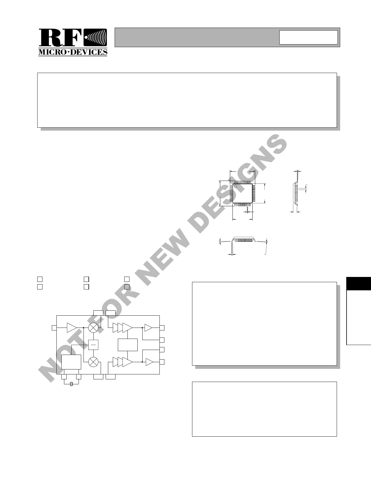
LNA IN 6
LNA
MOUT Q± IN Q±
1,2 47,48
IF Amp
Q Data Amp
39 Q DATA
+45°
-45°
RSSI
Gain Control
42 IF OUT Q
19 IF OUT I
PLL
Freq. Synth.
IF Amp
21 I DATA
I Data Amp
23 24
Ref
11,12 13,14
MOUT I± IN I±
Refer to the Detailed Functional Block Diagram for description of full functionality
.362
.346
.362
.346
.280
.272
7°MAX
0°MIN
.280
.272
.011
.007
.057
.053
.006
.002
.020
.031 .007
.021 MAX
Package Style: LQFP-48
Features
• FCC Part 15.247 Compliant
• Direct Conversion Receiver
• On-Chip 86 Channel Frequency
Synthesizer
• On-Chip Selectable IF Bandwidths
• 2.7V to 3.6V Operation
Ordering Information
RF2908
915MHz Spread Spectrum Receiver with PLL Fre-
quency Synthesizer
11
Functional Block Diagram
RF Micro Devices, Inc.
7628 Thorndike Road
Greensboro, NC 27409, USA
Tel (336) 664 1233
Fax (336) 664 0454
http://www.rfmd.com
Rev C1 010904
11-85
1 page 
RF2908
Pin
1
2
3
4
5
6
7
8
9
10
11
12
13
14
15
16
17
18
19
20
21
22
23
24
25
26
27
28
29
30
31
32
33
34
Function
MOUT Q-
MOUT Q+
MIX VCC
MIX GND
LNA GND
LNA IN
SW GND
LNA VCC
SW GND2
ATTN
MOUT I+
MOUT I-
IN I+
IN I-
GND2
DCFB I
VCC2
GND3
IF OUT I
VCC3
I DATA
RSSI I
OSC B
OSC E
LE
PLL CLK
PLL DATA
PLL GND
PLLD VCC
LO OUT B
RESNTR+
RESNTR-
LO OUT
DO
Description
Interface Schematic
The complementary quadrature phase signal output from the front-end
mixer. See pin 2.
The quadrature phase signal output from the front-end mixer.
Supply voltage for the front-end quadrature mixers.
Ground connection for the front-end quadrature mixers.
Ground connection for the low noise amplifier (LNA).
Input to the attenuator and LNA.
Ground connection for the input attenuator.
Supply voltage for the LNA.
Ground connection for the input attenuator.
Input attenuator control point. When connected “high”, the attenuator
adds 20dB of series attenuation. When connected “low”, the attenuator
adds 0dB of series attenuation.
The in-phase signal output from the front-end mixer.
The complementary in-phase signal output from the front-end mixer.
See pin 12.
Input for the in-phase IF channel.
Complementary input for the in-phase IF channel.
Ground for VCC2.
DC feedback capacitor for in-phase channel.
Power supply for VGA amplifier 3, differential to single-ended converter,
and post filter.
Ground for VCC3.
Analog signal IF output for in-phase channel.
Power supply for data amplifier.
Logic-level data output for the in-phase channel. This is a digital output
signal obtained from the output of a Schmitt trigger.
Received signal strength indicator for the in-phase channel.
Base connection point for external reference crystal. The reference
crystal is connected between this pin and ground.
Emitter connection point for external reference crystal. Feedback
capacitors are connected between this pin and ground.
Latches data entered into the serial port. Data is clocked into the latch
on the rising edge of LE. See table and timing diagram.
PLL shift register clock. The rising edges of this clocking signal load in
the serial data present at the PLL DATA input pin into the internal latch.
See table and timing diagram.
Input data for loading the counters. Clocked, serial data at this port is
presented to the shift register, then to the latch, and finally to the
counter. Each clock transition sends a single bit to the on-board 7-bit
shift register. The MSB is loaded first. See table and timing diagram.
Ground connection for the PLL.
Supply voltage for the PLL.
Complementary local oscillator output. See pin 33.
This port is used to supply DC voltage to the VCO as well as tune the
center frequency of the VCO.
This is the complementary port to pin 31. Refer to pin 31.
Local oscillator output.
Connection point for the loop filter.
11
Rev C1 010904
11-89
5 Page 
RF2908
Detailed Functional Block Diagram
LNA IN 6
SW GND1 7
SW GND2 9
LNA GND 5
PLL ON 35
RX ENABL 36
BW SEL2 37
BW SEL1 38
MIX VCC 3
MOUT I+ 11
MOUT I- 12
IN I+ 13
IN I- 14
OSC B 23
OSC E 24
10 8
LNA
-0.5/-20.5
4 1 2 48 47
44
+45°
-45°
0-25 dB
0-20 dB
-12-+12
17
17dB
6 dB
Chip
Control
20
Ref. Osc.
5-bit Counter
/32
902-928
MHz
300 kHz
VCO
Prescaler
32/33
Phase
Detector
Charge Pump
300 kHz
7-Bit Counter
/94
7-Bit Swallow
Counter
0-85
7
7-Bit
Latch
7 7-Bit Shift
Register
39 Q DATA
42 IF OUT Q
45 DCFB Q
22 RSSI I
41 VREF
40 RSSI Q
43 VGC
21 I DATA
19 IF OUT I
18 GND3
16 DCFB I
15 GND2
46 GND1
34 DO
26 PLL CLK
25 LE
27 PLL DATA
30 31
32 33 28 29
11
Rev C1 010904
11-95
11 Page | ||
| Páginas | Total 18 Páginas | |
| PDF Descargar | [ Datasheet RF2908.PDF ] | |
Hoja de datos destacado
| Número de pieza | Descripción | Fabricantes |
| RF2905 | 433/868/915MHZ FM/FSK/ASK/OOK TRANSCEIVER | RF Micro Devices |
| RF2908 | 915MHZ SPREAD SPECTRUM RECEIVER WITH PLL FREQUENCY SYNTHESIZER | RF Micro Devices |
| RF2909 | 3V 915MHZ SPREAD-SPECTRUM TRANSMITTER IC | RF Micro Devices |
| Número de pieza | Descripción | Fabricantes |
| SLA6805M | High Voltage 3 phase Motor Driver IC. |
Sanken |
| SDC1742 | 12- and 14-Bit Hybrid Synchro / Resolver-to-Digital Converters. |
Analog Devices |
|
DataSheet.es es una pagina web que funciona como un repositorio de manuales o hoja de datos de muchos de los productos más populares, |
| DataSheet.es | 2020 | Privacy Policy | Contacto | Buscar |