XM116 반도체 회로 부품 판매점
Diode Protected N-Channel Enhancement Mode MOSFET General Purpose Amplifier
|
|
|
Calogic LLC |
CORPORATION
Diode Protected N-Channel
Enhancement Mode MOSFET
General Purpose Amplifier
M116
FEATURES
Low IGSS
•• Integrated Zener Clamp for Gate Protection
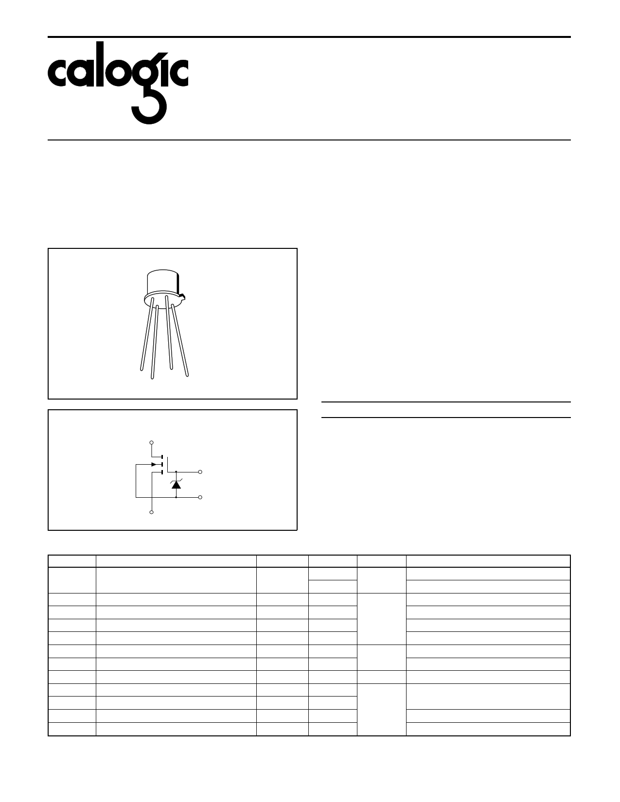
PIN CONFIGURATION
TO-72
1003Z
C
G
S
D
DEVICE SCHEMATIC
1
ABSOLUTE MAXIMUM RATINGS
(TA = 25oC unless otherwise specified)
Drain to Source Voltage. . . . . . . . . . . . . . . . . . . . . . . . . . . 30V
Gate to Drain Voltage . . . . . . . . . . . . . . . . . . . . . . . . . . . . 30V
Drain Current . . . . . . . . . . . . . . . . . . . . . . . . . . . . . . . . . 50mA
Gate Zener Current . . . . . . . . . . . . . . . . . . . . . . . . . . . ±0.1mA
Storage Temperature Range . . . . . . . . . . . . . -65oC to +200oC
Operating Temperature Range . . . . . . . . . . . -55oC to +125oC
Lead Temperature (Soldering, 10sec) . . . . . . . . . . . . . +300oC
Power Dissipation . . . . . . . . . . . . . . . . . . . . . . . . . . . . 225mW
Derate above 25oC . . . . . . . . . . . . . . . . . . . . . . . 2.2mW/oC
NOTE: Stresses above those listed under "Absolute Maximum
Ratings" may cause permanent damage to the device. These are
stress ratings only and functional operation of the device at these or
any other conditions above those indicated in the operational sections
of the specifications is not implied. Exposure to absolute maximum
rating conditions for extended periods may affect device reliability.
ORDERING INFORMATION
Part Package
M116
XM116
Hermetic TO-72
Sorted Chips in Carriers
Temperature Range
-55oC to +125oC
-55oC to +125oC
2
3
4 0330
ELECTRICAL CHARACTERISTICS (TA = 25oC and VBS = 0 unless otherwise specified)
SYMBOL
PARAMETER
rDS(on)
Drain Source ON Resistance
VGS(th)
BVDSS
BVSDS
BVGBS
ID(OFF)
IS(OFF)
IGSS
Cgs
Cgd
Cdb
Ciss
Gate Threshold Voltage
Drain-Source Breakdown Voltage
Source-Drain Breakdown Voltage
Gate-Body Breakdown Voltage
Drain Cuttoff Current
Source Cutoff Current
Gate-Body Leakage
Gate-Source (Note 1)
Gate-Drain Capacitance (Note 1)
Drain-Body Capacitance (Note 1)
Input Capacitance (Note 1)
MIN
MAX
UNITS
TEST CONDITIONS
100 Ω VGS = 20V, ID = 100µA
200 VGS = 10V, ID = 100µA
15
VGS = VDS, ID = 10µA
30 V ID = 1µA, VGS = 0
30 IS = 1µA, VGD = VBD = 0
30 60
IG = 10µA, VSB = VDB = 0
10 nA VDS = 20V, VGS = 0
10 VSD = 20V, VGD = VBD = 0
100 pA VGS = 20V, VDS = 0
2.5 VGB = VDB = VSB = 0, f = 1MHz
2.5 Body Guarded
pF
7 VGB = 0, VDB = 10V, f = 1MHz
10 VGB = 0, VDB = 10V, VBS = 0, f = 1MHz
NOTE 1: For design reference only, not 100% tested.
|
PDF 파일 내의 페이지 : 총 1 페이지
제조업체: Calogic LLC
( calogic )
XM116 mosfet
데이터시트 다운로드 :
[ XM116.PDF ]
[ XM116 다른 제조사 검색 ]
국내 전력반도체 판매점
상호 : 아이지 인터내셔날
전화번호 : 051-319-2877
[ 홈페이지 ]
IGBT, TR 모듈, SCR, 다이오드모듈, 각종 전력 휴즈
( IYXS, Powerex, Toshiba, Fuji, Bussmann, Eaton )
전력반도체 문의 : 010-3582-2743
관련 데이터시트
XM116
Diode Protected N-Channel Enhancement Mode MOSFET General Purpose Amplifier - Calogic LLC
