|
|
|
PDF 7545 Data sheet ( Hoja de datos )
| Número de pieza | 7545 | |
| Descripción | SINGLE-CHIP 8-BIT CMOS MICROCOMPUTER | |
| Fabricantes | Renesas | |
| Logotipo | ||
Hay una vista previa y un enlace de descarga de 7545 (archivo pdf) en la parte inferior de esta página. Total 30 Páginas | ||
|
No Preview Available !
7545 Group
SINGLE-CHIP 8-BIT CMOS MICROCOMPUTER
REJ03B0140-0106
Rev.1.06
Mar 07, 2008
DESCRIPTION
The 7545 Group is the 8-bit microcomputer based on the 740
family core technology.
The 7545 Group has an 8-bit timer, power-on reset circuit and the
voltage drop detection circuit. Also, Function set ROM is
equipped.
FEATURES
• Basic machine-language instructions .................................. 71
• The minimum instruction execution time .................... 2.00 µs
(at 4 MHz oscillation frequency for the shortest instruction)
• Memory size ROM ........................................ 4K to 60K bytes
RAM ............................................ 256, 512 bytes
• Programmable I/O ports ...................................................... 25
• Key-on wakeup input .................................................. 8 inputs
• LED output port ...................................................................... 8
• Interrupts.................................................... 7 sources, 7 vectors
• Timers .......................................................................... 8-bit × 3
• Carrier wave generating circuit .......1 channel (8-bit timer × 2)
• Clock generating circuit ........................................ Built-in type
(connect to external ceramic resonator or quartz-crystal
oscillator)
• Watchdog timer .........................................................16-bit × 1
• Power-on reset circuit............................................ Built-in type
• Voltage drop detection circuit................................ Built-in type
• Power source voltage
XIN oscillation frequency at ceramic/quartz-crystal oscillation
At 4 MHz .......................................... 1.8 to 3.6 V
• Power dissipation .......................................................... 1.8mW
• Operating temperature range .................................−20 to 85 °C
APPLICATION
Remote control transmit.
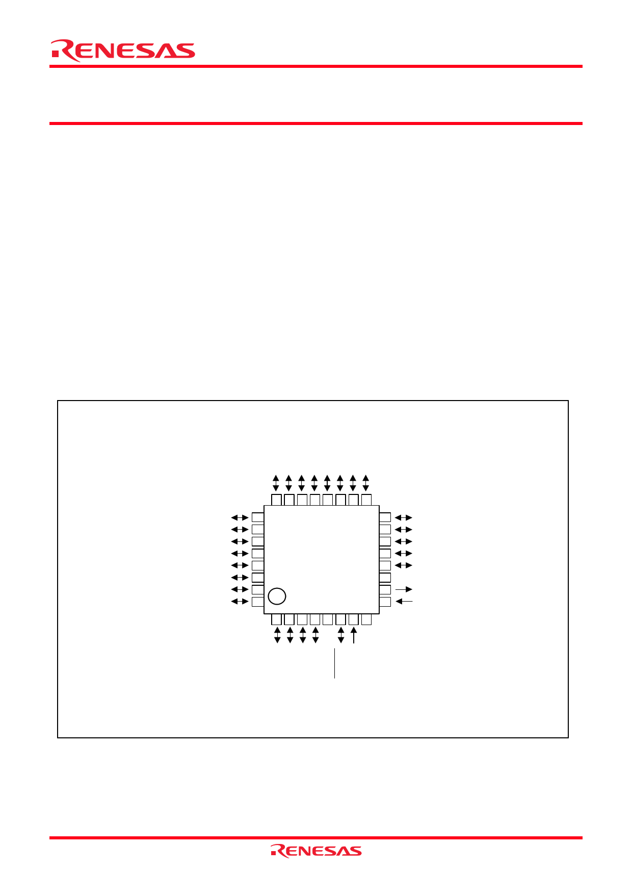
PIN CONFIGURATION (TOP VIEW)
http://www.DataSheet4U.net/
5/KEY5
6/KEY6
7/KEY7
0(LED0)/INT0
1(LED1)/INT1
2(LED2)
3(LED3)
4(LED4)
4
3
2
1
0
SS
OUT
IN
Fig. 1 Pin configuration (PLQP0032GB-A type)
Rev.1.06 Mar 07, 2008 Page 1 of 59
REJ03B0140-0106
datasheet pdf - http://www.DataSheet4U.net/
1 page 
7545 Group
http://www.DataSheet4U.net/
Fig. 4 Functional block diagram (PLQP0032GB-A package)
Rev.1.06 Mar 07, 2008 Page 5 of 59
REJ03B0140-0106
datasheet pdf - http://www.DataSheet4U.net/
5 Page 
7545 Group
[Processor status register (PS)]
Decimal correction is automatic in decimal mode. Only the
The processor status register is an 8-bit register consisting of
flags which indicate the status of the processor after an
ADC and SBC instructions can be used for decimal
arithmetic.
arithmetic operation. Branch operations can be performed by
testing the Carry (C) flag, Zero (Z) flag, Overflow (V) flag, or
the Negative (N) flag. In decimal mode, the Z, V, N flags are not
valid.
After reset, the Interrupt disable (I) flag is set to “1”, but all other
flags are undefined. Since the Index X mode (T) and Decimal
mode (D) flags directly affect arithmetic operations, they should
be initialized in the beginning of a program.
Bit 4: Break flag (B)
The B flag is used to indicate that the current interrupt was
generated by the BRK instruction. The BRK flag in the
processor status register is always “0”. When the BRK
instruction is used to generate an interrupt, the processor
status register is pushed onto the stack with the break flag set
to “1”. The saved processor status is the only place where the
break flag is ever set.
Bit 0: Carry flag (C)
The C flag contains a carry or borrow generated by the
arithmetic logic unit (ALU) immediately after an arithmetic
operation. It can also be changed by a shift or rotate
instruction.
Bit 5: Index X mode flag (T)
When the T flag is “0”, arithmetic operations are performed
between accumulator and memory. When the T flag is “1”,
direct arithmetic operations and direct data transfers are
enabled between memory locations.
Bit 1: Zero flag (Z)
The Z flag is set if the result of an immediate arithmetic
operation or a data transfer is “0”, and cleared if the result is
anything other than “0”.
Bit 6: Overflow flag (V)
The V flag is used during the addition or subtraction of one
byte of signed data. It is set if the result exceeds +127 to -
128. When the BIT instruction is executed, bit 6 of the
Bit 2: Interrupt disable flag (I)
The I flag disables all interrupts except for the interrupt
memory location operated on by the BIT instruction is stored
in the overflow flag.
generated by the BRK instruction. Interrupts are disabled
when the I flag is “1”.
When an interrupt occurs, this flag is automatically set to “1”
to prevent other interrupts from interfering until the current
interrupt is serviced.
Bit 7: Negative flag (N)
The N flag is set if the result of an arithmetic operation or
data transfer is negative. When the BIT instruction is
executed, bit 7 of the memory location operated on by the
BIT instruction is stored in the negative flag.
Bit 3: Decimal mode flag (D)
The D flag determines whether additions and subtractions are
executed in binary or decimal. Binary arithmetic is executed
when this flag is “0”; decimal arithmetic is executed when it
http://www.DataSheet4U.net/
is “1”.
Table 6 Set and clear instructions of each bit of processor status register
Set instruction
Clear instruction
C flag
SEC
CLC
Z flag
−
−
I flag
SEI
CLI
D flag
SED
CLD
B flag
−
−
T flag
SET
CLT
V flag
−
CLV
N flag
−
−
Rev.1.06 Mar 07, 2008 Page 11 of 59
REJ03B0140-0106
datasheet pdf - http://www.DataSheet4U.net/
11 Page | ||
| Páginas | Total 30 Páginas | |
| PDF Descargar | [ Datasheet 7545.PDF ] | |
Hoja de datos destacado
| Número de pieza | Descripción | Fabricantes |
| 7540 | SINGLE-CHIP 8-BIT CMOS MICROCOMPUTER | Renesas |
| 7545 | SINGLE-CHIP 8-BIT CMOS MICROCOMPUTER | Renesas |
| 75452 | MC75452 | ETC |
| 7545A | 12-Bit Buffered Multiplying Digital to Analog Converter | Maxwell Technologies |
| Número de pieza | Descripción | Fabricantes |
| SLA6805M | High Voltage 3 phase Motor Driver IC. |
Sanken |
| SDC1742 | 12- and 14-Bit Hybrid Synchro / Resolver-to-Digital Converters. |
Analog Devices |
|
DataSheet.es es una pagina web que funciona como un repositorio de manuales o hoja de datos de muchos de los productos más populares, |
| DataSheet.es | 2020 | Privacy Policy | Contacto | Buscar |