|
|
|
PDF A6264 Data sheet ( Hoja de datos )
| Número de pieza | A6264 | |
| Descripción | Automotive Stop/Tail LED Array Driver | |
| Fabricantes | Allegro MicroSystems | |
| Logotipo | ||
Hay una vista previa y un enlace de descarga de A6264 (archivo pdf) en la parte inferior de esta página. Total 15 Páginas | ||
|
No Preview Available !
www.DataSheet.co.kr
A6264
Automotive Stop/Tail LED Array Driver
Features and Benefits
▪ Total LED drive current up to 400 mA
▪ Current shared equally up to 100 mA by up to 4 strings
▪ 6 to 50 V supply
▪ Low dropout voltage
▪ LED output short-to-ground and thermal protection
▪ Enable input for PWM control
▪ Current slew rate limit during PWM
▪ Current set by reference resistor
▪ Automotive K-temperature range version (–40°C to 150°C):
contact factory for availability
Applications:
▪ Automotive tail, stop, and turn lights
Packages
10-pin MSOP with
exposed thermal pad
(suffix LY)
16-pin TSSOP with
exposed thermal pad
(suffix LP)
Not to scale
Description
TheA6264 is a linear, programmable current regulator providing
up to 100 mA from each of four outputs to drive arrays of high
brightness LEDs. The LED current can be switched between
high current and low current for stop/tail applications. The
two LED current levels from each output, accurate to 5%,
are set by two reference resistors. Current matching in each
string is better than 10% without the use of ballast resistors.
Driving LEDs with constant current ensures safe operation
with maximum possible light output.
For automotive applications, optimum performance is achieved
when driving 4 strings with 1 to 3 LEDs in each string, at a
total current of up to 100 mA in each string. Outputs can be
connected in parallel or left unused as required.
Short detection is provided to protect the LEDs and the A6264
during a short-to-ground at any LED output pin. An open LED
in any of the strings disables all outputs but can be overridden.
Shorted LED output pins or open LEDs are indicated by a
fault flag.
A temperature monitor is included to reduce the LED drive
current if the chip temperature exceeds a thermal threshold.
The device packages are a 10-pin MSOP (LY) and a 16-pin
TSSOP (LP), both with exposed pad for enhanced thermal
dissipation. They are lead (Pb) free, with 100% matte tin
leadframe plating.
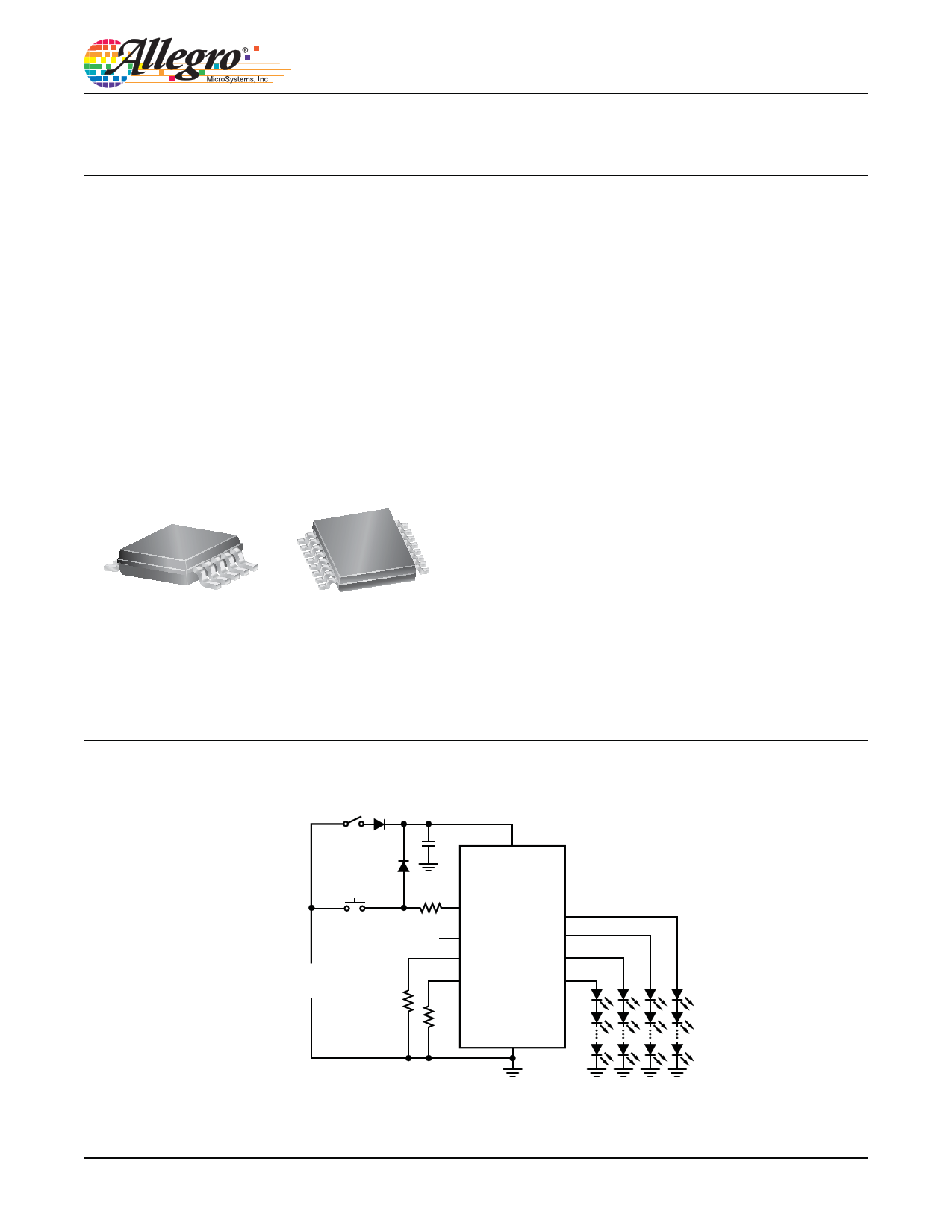
Typical Application Diagram
Tail Switch
Stop Switch
+
Automotive
12 V power net
–
VIN
A6264
FULL
LA1
FF LA2
IREFH
LA3
IREF
LA4
GND
A6264-DS
Datasheet pdf - http://www.DataSheet4U.net/
1 page 
www.DataSheet.co.kr
A6264
Automotive Stop/Tail LED Array Driver
Functional Description
The A6264 is a linear current regulator that is designed to pro-
vide drive current and protection for parallel strings of series-
connected high brightness LEDs in automotive applications. It
provides up to four matched programmable current outputs, at
up to 100 mA, with low minimum dropout voltages below the
main supply voltage. For 12 V power net applications optimum
performance is achieved when driving 4 strings of 1 to 3 LEDs,
at currents up to 100 mA per string.
The A6264 is specifically designed for use in stop/tail applica-
tions where the LED current is switched between a high current
(indicating stop or brake) and a lower current (for normal tail
light operation).
Current regulation is maintained and the LEDs protected during a
short to ground at any point in the LED string. A short to ground
on any regulator output terminal will disable that output and set
the fault flag. An open load on any output will set the fault flag
and disable all outputs. Remaining outputs can be re-enabled
by pulling the fault flag output low. Individual outputs can be
disabled by connecting the output to VIN.
Integrated thermal management reduces the regulated current
level at high internal junction temperatures to limit power dis-
sipation.
Pin Functions
VIN Supply to the control circuit and current regulators. A small
value ceramic bypass capacitor, typically 100 nF, should be con-
nected from close to this pin to the GND pin.
GND Ground reference connection. Should be connected directly
to the negative supply.
FULL Logic input to enable high LED current output. Open or
low sets LED current to the base current level. High sets LED
current to the sum of the base current level, and the additional
high current (see Detailed Description of Regulator Operation
section). Typically connected through a resistor to the stop switch
input.
IREF 1.2 V base current reference. Used for base (low) level
current output, IREF. Connect resistor, RREF, to GND to set this
reference current.
IREFH 1.2 V additional high current reference. Summed with
IREF for full current output. Connect resistor, RREFH, to GND to
set this reference current.
LA[1:4] Current source connected to the anode of the first LED in
each string. Connect directly to VIN to disable the respective out-
put. In this document “LAx” indicates any one of the four outputs.
FF Open drain fault flag, used with an external pull-up resistor,
to indicate open, short, or overtemperature conditions. FF is inac-
tive when a fault is present. During an open load condition, FF
can be pulled low to force the remaining outputs on.
LED Current Level
The LED current is controlled by four matching linear current
regulators between the VIN pin and each of the LAx outputs. The
basic equations that determine the nominal output current at each
LAx pin are:
Given FULL = low,
ILAx = 15
RREF
and, given FULL = high,
ILAx = 15 + 15
R RREF REFH
where ILAx is in mA, and RREF and RREFH are in kΩ.
(1)
In both cases, the output current may be reduced from the set
level by the thermal monitor circuit.
Conversely the reference resistors may be calculated from:
RREF =
15
ILAx(LO)
and
RREFH =
15
ILAx(HI) – ILAx(LO)
(2)
where ILAx(LO) is the required source current when FULL is low
and ILAx(HI) is the current when FULL is high. ILAx(x) are in mA,
and RREF and RREFH are in kΩ.
Allegro MicroSystems, Inc.
115 Northeast Cutoff
Worcester, Massachusetts 01615-0036 U.S.A.
1.508.853.5000; www.allegromicro.com
5
Datasheet pdf - http://www.DataSheet4U.net/
5 Page 
www.DataSheet.co.kr
A6264
Automotive Stop/Tail LED Array Driver
increases from 14 to 17 V. Without the thermal foldback feature
the temperature would continue to increase up to the thermal
shutdown temperature as shown by the dashed line. The solid line
shows the effect of the thermal foldback function in limiting the
temperature rise.
Figures 5 and 6 show the thermal effects where the thermal resis-
tance from the silicon to the ambient temperature is 40°C/W as
described below.
Thermal Dissipation
The amount of heat that can pass from the silicon of the A6264
to the surrounding ambient environment depends on the thermal
resistance of the structures connected to the A6264. The thermal
resistance, RθJA, is a measure of the temperature rise created by
power dissipation and is usually measured in degrees Celsius per
watt (°C/W).
The temperature rise, ΔT, is calculated from the power dissipated,
PD, and the thermal resistance, RθJA, as:
ΔT = PD × RθJA
(11)
A thermal resistance from silicon to ambient, RθJA, of approxi-
mately 40°C/W can be achieved by mounting the A6264 on a
standard FR4 double-sided printed circuit board (PCB) with a
copper area of a few square inches on each side of the board
under the A6264. Multiple thermal vias, as shown in figure 7,
help to conduct the heat from the exposed pad of the A6264 to the
copper on each side of the board. The thermal resistance can be
reduced by using a metal substrate or by adding a heatsink.
• For minimum supply voltage the limiting factor is the maximum
drop-out voltage of the regulator, where the difference between
the load voltage and the supply is insufficient for the regulator
to maintain control over the output current.
Minimum Supply Limit: Regulator Saturation Voltage
The supply voltage, VIN, is always the sum of the voltage drop
across the high-side regulator, VREG , and the forward voltage of
the LEDs in the string, VLED, as shown in figure 3.
VLED is constant for a given current and does not vary with
supply voltage. Therefore VREG provides the variable difference
between VLED and VIN . VREG has a minimum value below which
the regulator can no longer be guaranteed to maintain the output
current within the specified accuracy. This level is defined as the
regulator drop-out voltage, VDO.
The minimum supply voltage, below which the LED current does
not meet the specified accuracy, is therefore determined by the
sum of the minimum drop-out voltage, VDO , and the forward
voltage of the LEDs in the string, VLED . The supply voltage must
Supply Voltage Limits
In many applications, especially in automotive systems, the avail-
able supply voltage can vary over a two-to-one range, or greater
when double battery or load dump conditions are taken into con-
sideration. In such systems is it necessary to design the applica-
tion circuit such that the system meets the required performance
targets over a specified voltage range.
To determine this range when using the A6264 there are two
limiting conditions:
• For maximum supply voltage the limiting factor is the power
that can be dissipated from the regulator without exceeding the
temperature at which the thermal foldback starts to reduce the
output current below an acceptable level.
Figure 7. Board via layout for thermal dissipation: (top) LP package
(bottom) LY package.
Allegro MicroSystems, Inc.
115 Northeast Cutoff
Worcester, Massachusetts 01615-0036 U.S.A.
1.508.853.5000; www.allegromicro.com
11
Datasheet pdf - http://www.DataSheet4U.net/
11 Page | ||
| Páginas | Total 15 Páginas | |
| PDF Descargar | [ Datasheet A6264.PDF ] | |
Hoja de datos destacado
| Número de pieza | Descripción | Fabricantes |
| A6260 | High Brightness LED Current Regulator | Allegro MicroSystems |
| A6261 | Protected LED Array Driver | Allegro MicroSystems |
| A6262 | Automotive LED Array Driver | Allegro MicroSystems |
| A6264 | Automotive Stop/Tail LED Array Driver | Allegro MicroSystems |
| Número de pieza | Descripción | Fabricantes |
| SLA6805M | High Voltage 3 phase Motor Driver IC. |
Sanken |
| SDC1742 | 12- and 14-Bit Hybrid Synchro / Resolver-to-Digital Converters. |
Analog Devices |
|
DataSheet.es es una pagina web que funciona como un repositorio de manuales o hoja de datos de muchos de los productos más populares, |
| DataSheet.es | 2020 | Privacy Policy | Contacto | Buscar |