|
|
|
PDF BD6164GUT Data sheet ( Hoja de datos )
| Número de pieza | BD6164GUT | |
| Descripción | 320mA LED Camera Flash Driver | |
| Fabricantes | ROHM Semiconductor | |
| Logotipo | ||
Hay una vista previa y un enlace de descarga de BD6164GUT (archivo pdf) en la parte inferior de esta página. Total 21 Páginas | ||
|
No Preview Available !
Datasheet
320mA LED Camera Flash Driver
With I2C Compatible Interface
BD6164GUT
General Description
The BD6164GUT is 320mA Flash LED driver with
Synchronous rectification step up DC/DC converter that
can drive 1 Flash LED.
It is possible to choice flash and torch current by I2C I/F.
Features
Current regulation for LED
Flash LED Current driver
(260mA,280mA,300mA,320mA)
Assist Light Function LED Current driver
(52mA, 72mA)
High efficiency : 85%
(LED current 300mA, VBAT=3.6V, LED Vf=3.6V,
4MHz mode,Ta=25 oC)
I2C Control I/F
Synchronous rectification step-up DC/DC converter
High switching frequency 4MHz
Over Voltage Protection (OVP)
In-rush current prevention (Soft Start)
Over Current Protection (OCP)
Under Voltage Lockout (UVLO)
Over Temperature Protection (OTP)
Short-Circuit Fault detection (SCF)
Internal generated power supply
Key Specifications
Operating power supply voltage range: 2.7V to 4.5V
Quiescent Current:
1μA (Typ.)
Switching Frequency:
4.0MHz(Typ.)
Operating temperature range:
-30 to +85
Package
W(Typ.) D(Typ.) H (Max.)
VCSP60N1
1.10mm x 1.50mm x 0.675mm
Applications
Torch light and flash for camera of mobile phone
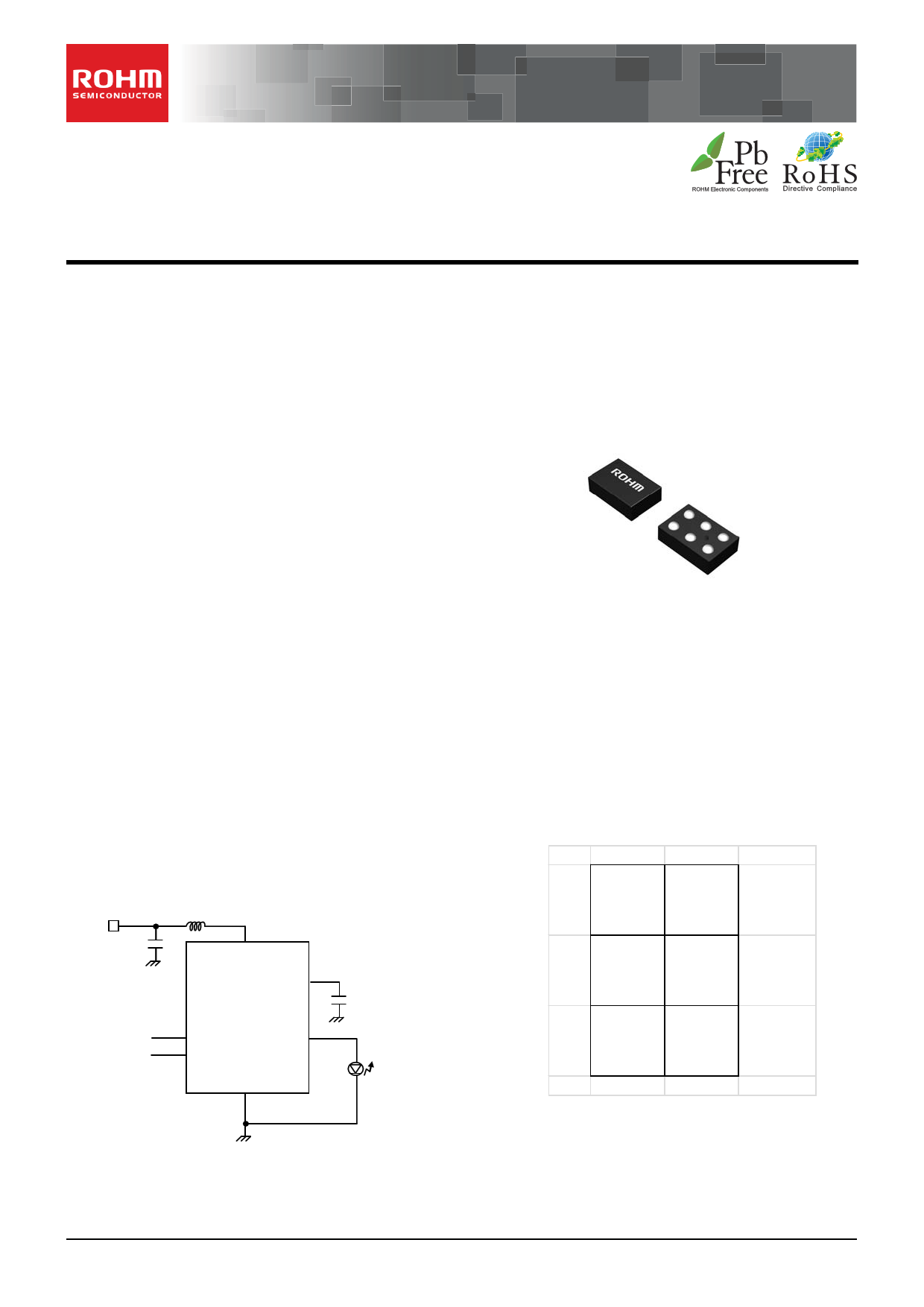
Typical Application Circuit and Block Diagram
Battery
2.2µF
1.0µH
SW
VOUT
BD6164GUT
SDA
SCL
LEDOUT
GND
2 x 1.5µF
Flash LED
Pn Configuration
BOTTOM VIEW
C SCL
SDA
B LEDOUT VOUT
A SW
1
GND
2
Product structure Silicon monolithic integrated circuit
www.rohm.com
© 2012 ROHM Co., Ltd. All rights reserved.
TSZ22111 14 001
This product is not designed protection against radioactive rays
1/17
TSZ02201-0G3G0C200280-1-2
21.Dec.2012 Rev.001
1 page 
BD6164GUT
Datasheet
◦ Writing protocol
A register address is transferred by the next 1 byte that transferred the slave address and the write-in command. The 3rd
byte writes data in the internal register written in by the 2nd byte, and after 4th byte or, the increment of register address is
carried out automatically. However, when a register address turns into the last address(07h), it is set to 00h by the next
transmission. After the transmission end, the increment of the address is carried out.
*1 *1
S X X X X X X X 0 A A7 A6 A5 A4 A3 A2 A1 A0 A D7 D6 D5 D4 D3 D2 D1 D0 A D7 D6 D5 D4 D3 D2 D1 D0 A P
slave address
register address
DATA
DATA
R/W=0(write)
from master to slave
from slave to master
register address
increment
A=acknowledge(SDA LOW)
A=not acknowledge(SDA HIGH)
S=START condition
P=STOP condition
*1: Write Timing
register address
increment
Figure 4. I2C Write protocol
◦ Reading protocol
It reads from the next byte after writing a slave address and R/W bit. The register to read considers as the following
address accessed at the end, and the data of the address that carried out the increment is read after it. If an address turns
into the last address(07h), the next byte will read out 00h. After the transmission end, the increment of the address is
carried out.
S X X X X X X X 1 A D7 D6 D5 D4 D3 D2 D1 D0 A
D7 D6 D5 D4 D3 D2 D1 D0 A P
slave address
DATA
DATA
R/W=1(read)
from master to slave
from slave to master
register address
increment
A=acknowledge(SDA LOW)
A=not acknowledge(SDA HIGH)
S=START condition
P=STOP condition
register address
increment
Figure 5. I2C Read protocol
◦ Multiple reading protocols
After specifying an internal address, it reads by repeated START condition and changing the data transfer direction. The
data of the address that carried out the increment is read after it. If an address turns into the last address, the next byte will
read out 00h. After the transmission end, the increment of the address is carried out.
S X X X X X X X 0 A A7 A6 A5 A4 A3 A2 A1 A0 A Sr X X X X X X X 1 A
slave address
register address
slave address
R/W=0(write)
R/W=1(read)
D7D6D5 D4D3D2 D1D0 A
D7D6 D5D4D3D2D1D0 A P
DATA
DATA
from master to slave
from slave to master
register address
increment
register address
increment
A=acknowledge(SDA LOW)
A=not acknowledge(SDA HIGH)
S=START condition
P=STOP condition
Sr=repeated START condition
Figure 6. I2C Multiple read protocol
As for reading protocol and multiple reading protocols, please do A(not acknowledge) after doing the final reading
operation. It stops with read when ending by A(acknowledge), and SDA stops in the state of Low when the reading data of
that time is 0. However, this state returns usually when SCL is moved, data is read, and A(not acknowledge)is done.
www.rohm.com
© 2012 ROHM Co., Ltd. All rights reserved.
TSZ22111 15 001
5/17
TSZ02201-0G3G0C200280-1-2
21.Dec.2012 Rev.001
5 Page 
BD6164GUT
Datasheet
2. Internal power supply
BD6164GUT has no separate supply for the internal circuitry generally known as “Vdd”. The internal circuitry of the chip is
supplied directly from the output voltage (VOUT). During battery-insertion, the VOUT node ramps up to battery voltage level
(PMOS switch is ON initially). When the main system is switched on (i.e. by H/W button), the I2C terminals are pulled-up,
which initializes the LED flash driver control core, after which it is goes into sleep mode, listening for I2C commands to be
activated. As soon as an I2C wake-up call from the main system is detected, the internal circuitry is enabled and the LED
flash driver goes into operational mode (see also item 6 on the next page).
L
SW
VOUT
Cont rol
Initially LOW
Initially LOW
LEDOUT
I2C I/F and Digital control
GND
SDA SCL
Any I2C ‘write command’ activates the internal blocks of the BD6164GUT, in order to be ready for LED activation. However,
if the write command is not immediately followed by a flash or assistant light command, please apply a read command to
ensure the IC is going back to low-current standby mode.
Figure 10. Internal power supply
www.rohm.com
© 2012 ROHM Co., Ltd. All rights reserved.
TSZ22111 15 001
11/17
TSZ02201-0G3G0C200280-1-2
21.Dec.2012 Rev.001
11 Page | ||
| Páginas | Total 21 Páginas | |
| PDF Descargar | [ Datasheet BD6164GUT.PDF ] | |
Hoja de datos destacado
| Número de pieza | Descripción | Fabricantes |
| BD6164GUT | 320mA LED Camera Flash Driver | ROHM Semiconductor |
| Número de pieza | Descripción | Fabricantes |
| SLA6805M | High Voltage 3 phase Motor Driver IC. |
Sanken |
| SDC1742 | 12- and 14-Bit Hybrid Synchro / Resolver-to-Digital Converters. |
Analog Devices |
|
DataSheet.es es una pagina web que funciona como un repositorio de manuales o hoja de datos de muchos de los productos más populares, |
| DataSheet.es | 2020 | Privacy Policy | Contacto | Buscar |