|
|
|
PDF AN027 Data sheet ( Hoja de datos )
| Número de pieza | AN027 | |
| Descripción | Applications for White LED Driver | |
| Fabricantes | AIC | |
| Logotipo | ||
Hay una vista previa y un enlace de descarga de AN027 (archivo pdf) en la parte inferior de esta página. Total 7 Páginas | ||
|
No Preview Available !
AN027
Applications for White LED Driver in Parallel vs. Series
Introduction
For the past few years there has been a huge
revolution in color LCD displayers for hand-held
devices, such as cellular phones, PDAs and DSCs.
White Light Emitting Diode (LED) Module, a new
technology for LCD displayers, plays an important role
in the applications powered by a single-cell Li-ion
battery. Due to the operating voltage limit (3.3V~4.2V)
of single-cell Li-ion battery, it cannot drive white LEDs,
which require a forward voltage at 3.6V.
Therefore, we need a boost circuit, which is powered
by a single-cell Li-ion battery, for white LEDs.
Generally in mobile phone applications, white LEDs
are usually used in two models-series and parallel.
This application note points out several differences
between these two models, and then gives
corresponding solutions.
The Model of White LEDs Driver
Parallel Model-Charge Pump Converter
For driving LEDs, fig.1 shows a parallel model
solution by using AIC1845 as a charge pump
converter, which needs only a few components to
achieve a regulated voltage. Several advantage and
disadvantage characteristics of this solution are as
follows:
Advantage
(1) Three ceramic capacitors are employed to
regulate voltage for driving LEDs with low profile
package, which is suitable for miniature
equipments.
(2) No coil, which may result in noise, is needed to
boost voltage for the charge pump converter. Due
to the advantage, EMI may not happen to mobile
phone application.
Disadvantage
(1) Disproportionate brightness may result from
different forward voltage of each LED, even
though constant voltage provided.
(2) Compare to solutions in serial with same input
voltage, parallel solution has relatively low
efficiency because of the regulation of output.
1 -Cell
Li-ion
Battery
CIN
2.2µF
1 VOUT
2
GND
3 SHDN
R1 680
6
C+
5
VIN
4
C-
COUT
2.2µF
CFLY
0.22µF
5VOUT
LED1 LED2 LED3 LED4
AIC1845
Fig.1 Parallel White LEDs Driver
October, 2003
1
1 page 
AN027
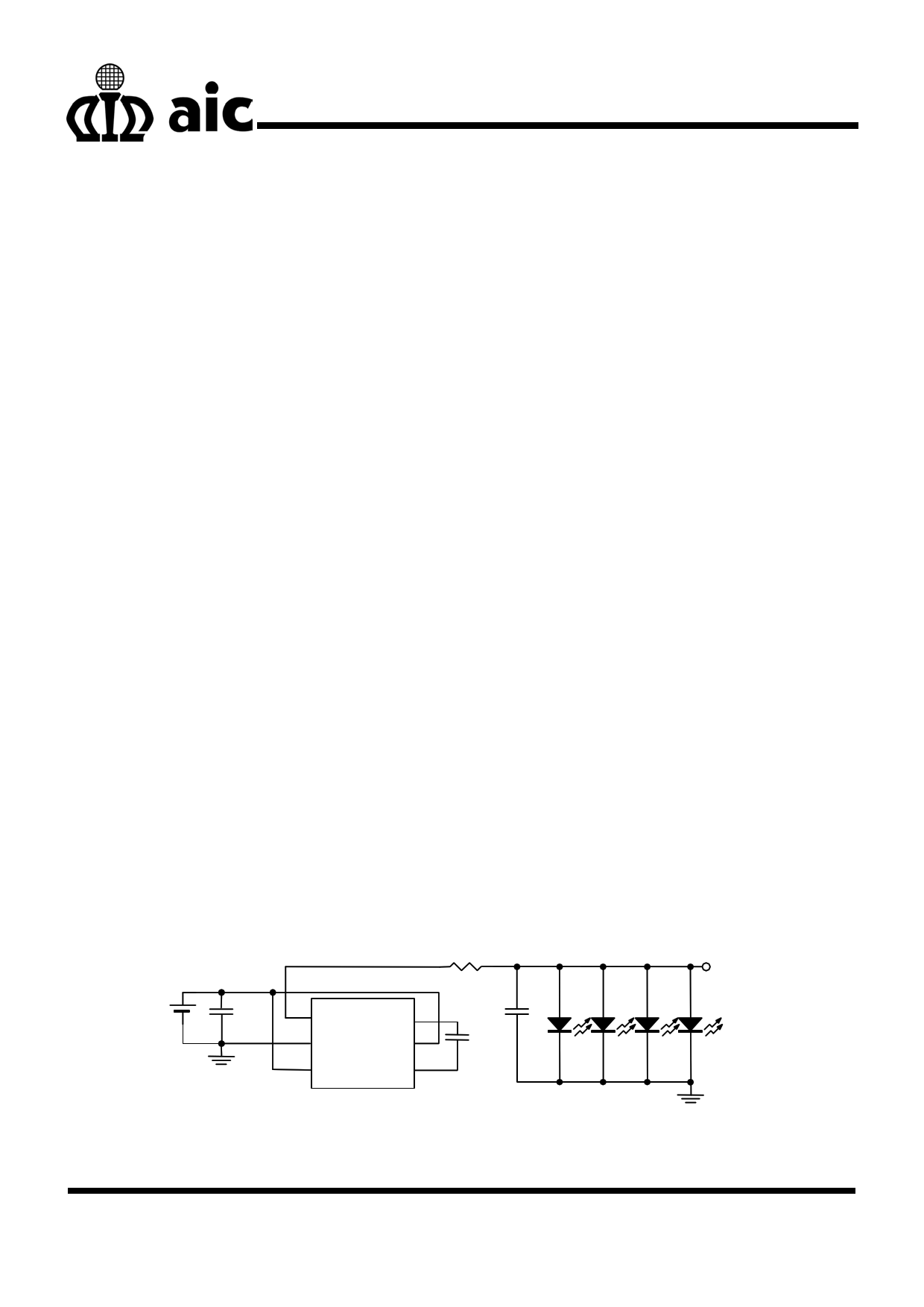
Brightness Control
As we know, current flows through LEDs will affect its
brightness. This principle can be used to control the
brightness of displayer. The followings describe
suggested methods to control the brightness of LEDs
in parallel and series applications.
Charge Pump Converter-AIC1845
As Fig.8 shows, a PWM signal, of which frequency
ranges from 50Hz to 100Hz, connects at SHDN pin
that controls the brightness by adjusting its duty cycle.
When the signal gets high, the device gets high also,
and then output current flows through the LEDs, and
vice versa. 100% duty cycle results in maximum
brightness, and 0% duty cycle causes darkness.
PWM signal
VIN VOUT
SHDN
C+
GND C-
AIC1845
R1 680
C
2.2µF LED1 LED2 LED3
5VOU
LED4
Fig. 8 Brightness Control in Parallel Application
Inductor Boost Converter-AIC1896
For series applications, several methods, as below,
are solutions for brightness control.
Solution with PWM Signals
Brightness can be controlled either by connecting a
PWM signal, of which frequency ranges from 1kHz to
10kHz, at SHDN pin directly, or by adding a resistor
at FB pin. If SHDN is used (Fig.9 (A)), the increase
of duty cycle enhances brightness. And when
application with FB pin used (Fig.9 (B)), brightness is
weakened by an increasing duty cycle.
PWM
AIC1896
IN LX
/SHDN FB
SS GND
C2
0.033µ
ZD1
R2
1K
R1
62
(A)
Fig. 9 Brightness Control by a PWM Signal
Solution with DC Voltage
As the current flowing through LEDs is a factor to
brightness, we use a variable DC voltage to adjust the
voltage across R1, and furthermore, the current gets
adjusted. As Fig.10 illustrates, as the voltage drop on
R3 increases, the voltage drop on R1 gets decreasing,
5
5 Page | ||
| Páginas | Total 7 Páginas | |
| PDF Descargar | [ Datasheet AN027.PDF ] | |
Hoja de datos destacado
| Número de pieza | Descripción | Fabricantes |
| AN020 | The Power Management of PDA | AIC |
| AN021 | A Handy Method to Obtain Satisfactory Response of Buck Converter | AIC |
| AN022 | High Side Driver | AIC |
| AN023 | An Useful Model for Charge Pump Converter | AIC |
| Número de pieza | Descripción | Fabricantes |
| SLA6805M | High Voltage 3 phase Motor Driver IC. |
Sanken |
| SDC1742 | 12- and 14-Bit Hybrid Synchro / Resolver-to-Digital Converters. |
Analog Devices |
|
DataSheet.es es una pagina web que funciona como un repositorio de manuales o hoja de datos de muchos de los productos más populares, |
| DataSheet.es | 2020 | Privacy Policy | Contacto | Buscar |