|
|
|
PDF ZL40515 Data sheet ( Hoja de datos )
| Número de pieza | ZL40515 | |
| Descripción | (ZL40511 / ZL40515) Dual Output DVD and CD 4 Channel Laser Diode Drivers | |
| Fabricantes | Zarlink Semiconductor | |
| Logotipo | ||
Hay una vista previa y un enlace de descarga de ZL40515 (archivo pdf) en la parte inferior de esta página. Total 30 Páginas | ||
|
No Preview Available !
www.DataSheet4U.com
Features
• Single 5 V supply (±10%)
• 150 mA low-noise read channel with 100 x
current gain
• Three 500 mA write channels with 240 x gain
• Combined channel output 700 mA
• Dual output for DVD/CD laser
• Rise and fall times 1 ns typical
• Oscillator, 500 MHz, 100 mA with external
resistor control of frequency and amplitude
• Power Up/Down control
• CMOS control signals
• > 2 kV ESD
• Low Rth QFN package
• Contact Zarlink for available Custom Gain and
Input Impedance options
19 PWR_UP
20 INR
21 IN2
GND
22 IN3
GND
22 IN4
GND
24 GND_IN GND
1 /EN2
2 N/C
3 /EN3
4 GND
5 /EN4
6 N/C
7 VCC_IN
8 OSCEN
ZL40511/15
Dual Output DVD and CD
4 Channel Laser Diode Drivers
Data Sheet
August 2006
ZL40511LDE
ZL40511LDF
ZL40511LDG
ZL40515LDE
ZL40515LDF
ZL40515LDG
Ordering Information
24 Pin QFN
24 Pin QFN
24 Pin QFN
24 Pin QFN
24 Pin QFN
24 Pin QFN
Tubes, Bake & Drypack
Tape & Reel
Trays, Bake & Drypack
Tubes, Bake & Drypack
Tape & Reel
Trays, Bake & Drypack
-40°C to +85°C
Applications
• DVD±RW/RAM
• DVD±R
• CD-RW
• CD-R
• Write optical drives
• Laser Diode current switch
• Supports double density DVD
VCC_A 18
OUTA 17
GND 16
OUTB 15
VCC_B 14
RFA
RFB RSA
RSB
SELA
9 10
11 12
13
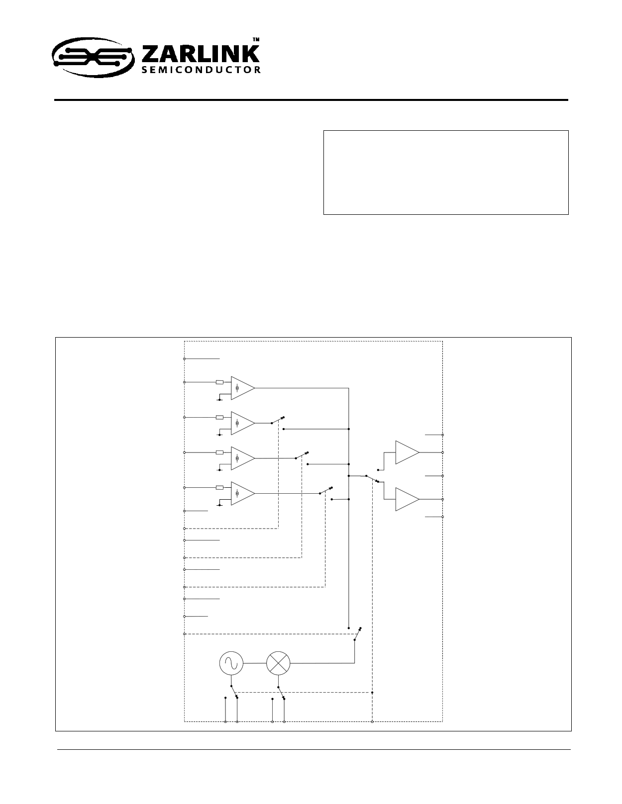
Figure 1 - Functional Block Diagram
1
Zarlink Semiconductor Inc.
Zarlink, ZL and the Zarlink Semiconductor logo are trademarks of Zarlink Semiconductor Inc.
Copyright 2004-2006, Zarlink Semiconductor Inc. All Rights Reserved.
1 page 
ZL40511/15
Data Sheet
1.0 Application Notes
1.1 Read and Write Channel Operation
The read channel is activated by applying a 'High' signal to the PWR_UP pin. In this mode, the fast write channels
can be enabled by applying a 'Low' signal to the respective write enable pins (/EN2), (/EN3) or (/EN4). The output
currents of the four channels are summed together and output as a composite signal at either OUTA (if SELA select
is 'High') or OUTB (if SELA select is 'Low'). This provides the ability to drive two different laser diodes with just one
ZL40511/15.
Voltage control of the channel reference inputs (INR, IN2, IN3 and IN4) can be achieved quite easily using an
external resistor Rref in series with the reference channel input to convert a given reference potential Vref to an input
current, Iin:
I in
=
Vref ,
Rref + Rin
where Rin is the input impedance of the respective reference channel.
1.2 On-chip RF Oscillator
An on-chip RF oscillator is enabled if OSCEN = 'High', and its output signal is added to the appropriate current
output (OUTA, if SELA select is 'High', or OUTB, if SELA select is 'Low'). The oscillator amplitude is set by an
external resistor from RSA or RSB to GND. Its frequency is set by an external resistor RFA or RFB to GND. RSA
and RFA are selected when SELA is ‘High’.
The oscillator signal is summed with the programmed Write and Read levels before amplification to the output. The
oscillator signal has zero DC level and +1_pt to –1_pt signal swing. Consequently, if the programmed DC level from
the Write and Read Channels is less than the PK level programmed for the Oscillator, the combined signal will be
clipped on the negative cycle of the signal. This will increase the harmonic content of the output signal and reduce
the pk to pk amplitude output.
1.3 Thermal Considerations
Package thermal resistance is 40°C/W under the EIA/JESD51-3 compliant PCB test board condition.
Users should ensure that the junction temperature does not exceed 150°C. Thermal resistance from junction to
case and to ambient is very much dependent on how the IC is mounted onto the board, on the PCB layout and on
any heat extraction arrangements.
Power consumption and system ambient operating temperature limits should be noted and careful thermal gradient
calculations undertaken to ensure that the junction temperature never exceeds 150°C.
5
Zarlink Semiconductor Inc.
5 Page 
5.0 Pin List
ZL40511/15
Data Sheet
Pin No.
1
2
3
4
5
6
7
8
9
10
11
12
13
14
15
16
17
18
19
20
21
22
23
24
Pin name
/EN2
NC
/EN3
NC
/EN4
NC
VCC_IN
OSCEN
RFA
RFB
RSA
RSB
SELA
VCC_B
OUTB
GND
OUTA
VCC_A
PWR_UP
INR
IN2
IN3
IN4
GND_IN
Type
LVDS
LVDS
LVDS
LVDS
LVDS
LVDS
supply
digital
analog
analog
analog
analog
digital
supply
analog
supply
analog
supply
digital
analog
analog
analog
analog
supply
Function
Digital control input for channel 2 (active low)
No internal connection
Digital control input for channel 3 (active low)
Ground
Digital control input for channel 4 (active low)
No internal connection
+5 V Input power supply
Oscillator enable control input, high active (TTL)
Resistor to GND sets oscillator frequency when SELA = ’High’
Resistor to GND sets oscillator frequency when SELA = ’Low’
Resistor to GND sets oscillator amplitude when SELA = ’High’
Resistor to GND sets oscillator amplitude when SELA = ’Low’
Output select input; 'High' selects OUTA, 'Low' selects OUTB (TTL)
Output B Vcc
Current output source B
Ground
Current output source A
Output A Vcc
Digital chip enable control input, high active (CMOS)
Current input, Rin = 400 Ohms to GND
Current input, Rin = 250 Ohms to GND (Optional 500 Ohms)
Current input, Rin = 250 Ohms to GND (Optional 500 Ohms)
Current input, Rin = 250 Ohms to GND (Optional 500 Ohms)
Ground for input circuit
11
Zarlink Semiconductor Inc.
11 Page | ||
| Páginas | Total 30 Páginas | |
| PDF Descargar | [ Datasheet ZL40515.PDF ] | |
Hoja de datos destacado
| Número de pieza | Descripción | Fabricantes |
| ZL40510 | (ZL40510 / ZL40514) Dual Output DVD and CD 4 Channel Laser Diode Drivers | Zarlink Semiconductor |
| ZL40511 | (ZL40511 / ZL40515) Dual Output DVD and CD 4 Channel Laser Diode Drivers | Zarlink Semiconductor |
| ZL40514 | (ZL40510 / ZL40514) Dual Output DVD and CD 4 Channel Laser Diode Drivers | Zarlink Semiconductor |
| ZL40515 | (ZL40511 / ZL40515) Dual Output DVD and CD 4 Channel Laser Diode Drivers | Zarlink Semiconductor |
| Número de pieza | Descripción | Fabricantes |
| SLA6805M | High Voltage 3 phase Motor Driver IC. |
Sanken |
| SDC1742 | 12- and 14-Bit Hybrid Synchro / Resolver-to-Digital Converters. |
Analog Devices |
|
DataSheet.es es una pagina web que funciona como un repositorio de manuales o hoja de datos de muchos de los productos más populares, |
| DataSheet.es | 2020 | Privacy Policy | Contacto | Buscar |