|
|
|
PDF A5366 Data sheet ( Hoja de datos )
| Número de pieza | A5366 | |
| Descripción | Photoelectric Smoke Detector | |
| Fabricantes | Allegro | |
| Logotipo | ||
Hay una vista previa y un enlace de descarga de A5366 (archivo pdf) en la parte inferior de esta página. Total 13 Páginas | ||
|
No Preview Available !
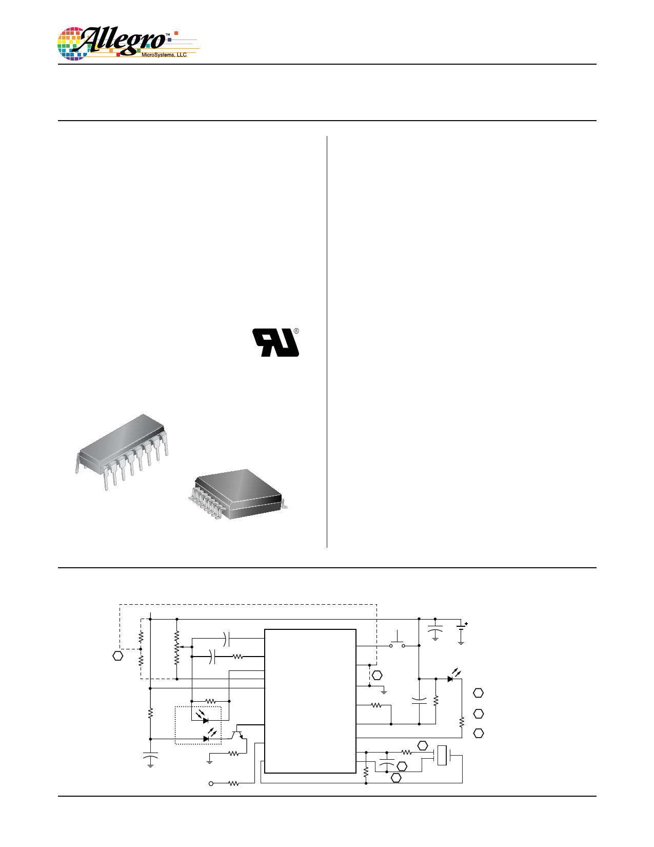
A5366
Photoelectric Smoke Detector
with Interconnect and Timer
Features and Benefits
▪ Low average standby current for long battery life
▪ Interconnect up to 50 detectors
▪ Piezoelectric horn driver
▪ Low battery detection (all internal)
▪ Chamber sensitivity test and alarm
▪ Power-on reset (POR)
▪ Internal timer and control for reduced sensitivity mode
▪ Built-in circuits to reduce false triggering
▪ 6 to 12 V operating range
▪ ESD protection circuitry on all pins
▪ Temporal Horn Pattern, per UL217, NFPA72, and ISO8201
▪ UL Recognized for UL217 or UL268 applications
Packages:
16-pin DIP
(Package A)
16-pin SOICW
(Package LW)
Not to scale
Description
The A5366 is a low-current BiCMOS circuit providing all of
the required features for a photoelectric type smoke detector.
This device can be used with an infrared photoelectric chamber
to sense scattered light from smoke particles. A networking
capability allows as many as 50 units to be interconnected so that
if any unit senses smoke all units will sound an alarm. Special
features are incorporated in the design to facilitate calibration
and testing of the finished detector. The device is recognized by
Underwriters Laboratories for use in smoke alarms that comply
with Standard UL217, or UL268, per file #S2113.
A variable-gain photoamplifier can be directly interfaced to
an infrared emitter-detector pair. The amplifier gain levels are
determined by two external capacitors and are internally selected
depending on the operating mode. Low gain is selected during
standby and timer modes. During a local alarm, this low gain
is increased (internally) by approximately 10% to reduce false
triggering. High gain is used during pushbutton test and to
periodically monitor the chamber sensitivity during standby.
The internal oscillator and timing circuitry keep standby power
to a minimum by sensing for smoke for only 100 μs every 10 s.
A special three-stage–speedup sensing scheme is incorporated
to minimize the time to an audible alarm and also to reduce
false triggering. Chamber sensitivity is periodically monitored
and two consecutive cycles of degraded sensitivity are required
for a warning signal (chirp) to occur.
The A5366 is supplied in a 16-pin dual in-line plastic package
(suffix A), and for surface mount, a 16-pin SOICW (suffix
LW). The lead (Pb) free versions (suffix –T) have 100% matte-
tin leadframe plating. The devices are rated for continuous
operation over the temperature range of –25°C to 75°C.
Typical Application Diagram
Rx1
A Rx2
26110.11-DS, Rev. G
VDD
8.2 kΩ
5 kΩ
4.7 kΩ
0.047 μF
560 Ω
4700 pF
200 kΩ
1 kΩ
Smoke
Chamber
100 μF
22 Ω
To / from
other units
220 Ω
1 C1
2 C2
A5366
3
4
DETECT
STROBE
5 VDD
TEST 16
HUSH 15
VSS 14
Push-to-Test
9V
22 μF
B Red LED
1500 pF
TIMING RES 13
100 kΩ
10 MΩ
6 IRED
OSC CAP 12
330 Ω
7 I/O
8 HORN1
LED 11
FEEDBACK 10
HORN2 9
220 kΩ C
1000 pF
C Piezo Horn
1.5 MΩ C
A Connect to allow timer mode
("hush") operation
B Connect HUSH to VSS
to disable timer mode
C Value of component can vary,
based on the piezoelectric horn used
1 page 
A5366
Photoelectric Smoke Detector
with Interconnect and Timer
DC ELECTRICAL CHARACTERISTICS (continued) at TA = –25°C to 75°C1, VSS = 0 V, in typical application (unless otherwise noted)
Characteristic
Line Regulation
IRED Temperature Coefficient
High-Level Output Current
OFF Leakage Current High
OFF Leakage Current Low
Low-Battery Alarm Threshold
Symbol
ΔVIRED(ΔVDD)
αIRED
IOH
IOZ
IOZ
VDD(th)
Test Conditions
Active, VDD = 6 to 12 V
VDD = 6 to 12 V
VDD = Alarm, I/O active,VO = VDD – 2 V
VO = VDD
VO = VSS
Common Mode Voltage
VIC Any alarm condition
Test Pin
6
6
7
11, 13
11, 13
5
1, 2, 3
VDD
–
9
12
12
–
-
Min.
–
–
–4.0
–
–
6.9
VDD
–4
Typ.2
–35
0.40
–
–
–
7.2
–
Max.
–
–
–
1.0
–1.0
7.5
VDD
–2
Units
dB
%/°C
mA
μA
μA
V
V
Smoke Comparator
Reference Voltage
VREF
Any alarm condition
Internal
-
VDD
– 3.7
–
VDD
– 3.3
V
1Limits over the operating temperature range are based on characterization data. Characteristics are production tested at 25°C only.
2Typical values are at 25°C and are given for circuit design information only.
AC ELECTRICAL CHARACTERISTICS at TA = –25°C to 75°C1. VSS = 0 V, in typical application (unless otherwise noted)
Characteristic
Oscillator Period
LED Pulse Period
Symbol
tosc
tled1
tled3
tled4
Test Conditions
No local or remote smoke
Local smoke
Remote smoke only
Test Pin
12
11
11
11
VDD
9
9
9
9
Min.
9.4
39
0.45
–
Typ.2
10.5
–
0.50
No LED
Pulses
LED Pulse Width
STROBE Pulse Period
tled6
tled7
tw(led)
tst1
tst2
tst3
tst4
tst5
Pushbutton test, induced alarm
Timer mode, no alarm
No local or remote smoke
After 1 of 3 valid samples
After 2 of 3 valid samples and during local
alarm
Remote smoke only
Chamber test or low battery test, no local
alarm
11 9 0.45 0.50
11 9 9.67 10.75
11 9 9.5 –
4 9 9.6 –
4 9 1.8 2.0
4 9 0.8 1.0
4 9 7.2 8.0
4 9 38.9 –
STROBE Pulse Width
tst6 Pushbutton test, induced alarm
tw(st)
4 9 225 252
4 9 9.5 –
Max.
11.5
48
0.55
–
0.55
11.83
11.5
11.9
2.2
1.1
8.9
47.1
278
11.5
Units
ms
s
s
s
s
s
ms
s
s
s
s
s
ms
ms
Continued on the next page…
Allegro MicroSystems, LLC
115 Northeast Cutoff
Worcester, Massachusetts 01615-0036 U.S.A.
1.508.853.5000; www.allegromicro.com
5
5 Page 
A5366
Photoelectric Smoke Detector
with Interconnect and Timer
Local Smoke Detection Alarm Condition
IRED Pin
1st strobe with smoke
3rd strobe with smoke
tst2, t ired2
tst3, tired3
tst3, tired3
STROBE Pin
LED Pin
tw(led)
LED on
LED off (High-Z)
ton(horn)
Horn Enable
tled3
toff2(horn)
I/O Pin
(Output)
3rd strobe without smoke
tw(st)
toff1(horn)
tdump
I/O Charge Dump
Remote Alarm Condition
STROBE Pin
LED Pin
Horn Enable
I/O Pin
tw(st)
LED off (High-Z)
ton(horn)
tr(io)
tst4, tired4
toff2(horn)
(Input)
Test Alarm Mode
STROBE Pin
LED Pin
TEST Pin
Horn Enable
tw(st)
tw(led)
LED on
LED off (High-Z)
ton(horn)
I/O Pin
tst6, tired6
tled6
toff2(horn)
(Output)
toff1(horn)
toff1(horn)
tdump
I/O Charge Dump
Allegro MicroSystems, LLC
115 Northeast Cutoff
Worcester, Massachusetts 01615-0036 U.S.A.
1.508.853.5000; www.allegromicro.com
11
11 Page | ||
| Páginas | Total 13 Páginas | |
| PDF Descargar | [ Datasheet A5366.PDF ] | |
Hoja de datos destacado
| Número de pieza | Descripción | Fabricantes |
| A5364 | Ionization Smoke Detector | Allegro |
| A5364CA | Ionization Smoke Detector | Allegro MicroSystems |
| A5366 | Photoelectric Smoke Detector | Allegro |
| A5366CA | Photoelectric Smoke Detector | Allegro MicroSystems |
| Número de pieza | Descripción | Fabricantes |
| SLA6805M | High Voltage 3 phase Motor Driver IC. |
Sanken |
| SDC1742 | 12- and 14-Bit Hybrid Synchro / Resolver-to-Digital Converters. |
Analog Devices |
|
DataSheet.es es una pagina web que funciona como un repositorio de manuales o hoja de datos de muchos de los productos más populares, |
| DataSheet.es | 2020 | Privacy Policy | Contacto | Buscar |