|
|
|
PDF G4PSC71UD Data sheet ( Hoja de datos )
| Número de pieza | G4PSC71UD | |
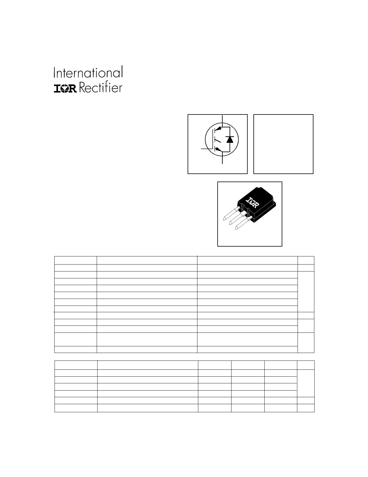
| Descripción | IRG4PSC71UD | |
| Fabricantes | International Rectifier | |
| Logotipo | ||
Hay una vista previa y un enlace de descarga de G4PSC71UD (archivo pdf) en la parte inferior de esta página. Total 10 Páginas | ||
|
No Preview Available !
PD - 91682A
IRG4PSC71UD
INSULATED GATE BIPOLAR TRANSISTOR WITH
UltraFast CoPack IGBT
ULTRAFAST SOFT RECOVERY DIODE
Features
• Generation 4 IGBT design provides tighter
parameter distribution and higher efficiency
(minimum switching and conduction losses) than
prior generations
• IGBT co-packaged with HEXFRED ultrafast, ultrasoft
recovery anti-parallel diodes for use in bridge
configurations
• Industry-benchmark Super-247 package with
higher power handling capability compared to
same footprint TO-247
• Creepage distance increased to 5.35mm
C
G
E
n-channel
VCES = 600V
VCE(on) typ. = 1.67V
@VGE = 15V, IC = 60A
Benefits
• Generation 4 IGBT's offer highest efficiencies
available
• Maximum power density, twice the power
handling of TO-247, less space than TO-264
• IGBTs optimized for specific application conditions
• HEXFRED diodes optimized for performance with IGBTs
• Cost and space saving in designs that require
multiple, paralleled IGBTs
Absolute Maximum Ratings
Parameter
VCES
Collector-to-Emitter Voltage
IC @ TC = 25°C
IC @ TC = 100°C
ICM
ILM
IF @ TC = 100°C
IFM
VGE
PD @ TC = 25°C
PD @ TC = 100°C
TJ
TSTG
Continuous Collector Current
Continuous Collector Current
Pulsed Collector Current
Clamped Inductive Load Current
Diode Continuous Forward Current
Diode Maximum Forward Current
Gate-to-Emitter Voltage
Maximum Power Dissipation
Maximum Power Dissipation
Operating Junction and
Storage Temperature Range
Soldering Temperature, for 10 sec.
Thermal Resistance\ Mechanical
RθJC
RθJC
RθCS
RθJA
www.irf.com
Parameter
Junction-to-Case - IGBT
Junction-to-Case - Diode
Case-to-Sink, flat, greased surface
Junction-to-Ambient, typical socket mount
Recommended Clip Force
Weight
SUPER - 247
Max.
600
85
60
200
200
60
350
± 20
350
140
-55 to +150
300 (0.063 in. (1.6mm) from case)
Units
V
A
V
W
°C
Min.
–––
–––
–––
–––
20.0(2.0)
–––
Typ.
–––
–––
0.24
–––
–––
6 (0.21)
Max.
0.36
0.69
–––
38
–––
–––
Units
°C/W
N (kgf)
g (oz)
1
5/12/99
1 page 
IRG4PSC71UD
14000
12000
10000
8000
VGE = 0V, f = 1MHz
Cies = Cge + Cgc , Cce SHORTED
Cres = Cgc
Coes = Cce + Cgc
Cies
6000
4000
2000
Coes
Cres
0
1 10 100
VCE , Collector-to-Emitter Voltage (V)
Fig. 7 - Typical Capacitance vs.
Collector-to-Emitter Voltage
12.0
VCC = 480V
VGE = 15V
11.0 TJ = 25 ° C
IC = 60A
10.0
9.0
8.0
7.0
6.0
5.0
0
10 20 30 40
RGR,GG, aGtaeteRReseissistatannccee ( Ω )
50
Fig. 9 - Typical Switching Losses vs. Gate
Resistance
www.irf.com
20
VCC = 400V
I C = 60A
16
12
8
4
0
0 100 200 300 400
QG , Total Gate Charge (nC)
Fig. 8 - Typical Gate Charge vs.
Gate-to-Emitter Voltage
100
RG = 55..00ΩOhm
VGE = 15V
VCC = 480V
IC = 120 A
10
IC = 60 A
IC = 30 A
1
-60 -40 -20 0 20 40 60 80 100 120 140 160
TJ , Junction Temperature °( C )
Fig. 10 - Typical Switching Losses vs.
Junction Temperature
5
5 Page | ||
| Páginas | Total 10 Páginas | |
| PDF Descargar | [ Datasheet G4PSC71UD.PDF ] | |
Hoja de datos destacado
| Número de pieza | Descripción | Fabricantes |
| G4PSC71UD | IRG4PSC71UD | International Rectifier |
| Número de pieza | Descripción | Fabricantes |
| SLA6805M | High Voltage 3 phase Motor Driver IC. |
Sanken |
| SDC1742 | 12- and 14-Bit Hybrid Synchro / Resolver-to-Digital Converters. |
Analog Devices |
|
DataSheet.es es una pagina web que funciona como un repositorio de manuales o hoja de datos de muchos de los productos más populares, |
| DataSheet.es | 2020 | Privacy Policy | Contacto | Buscar |