|
|
|
PDF LMK04800 Data sheet ( Hoja de datos )
| Número de pieza | LMK04800 | |
| Descripción | Low-Noise Clock Jitter Cleaner | |
| Fabricantes | National Semiconductor | |
| Logotipo | ||
Hay una vista previa y un enlace de descarga de LMK04800 (archivo pdf) en la parte inferior de esta página. Total 30 Páginas | ||
|
No Preview Available !
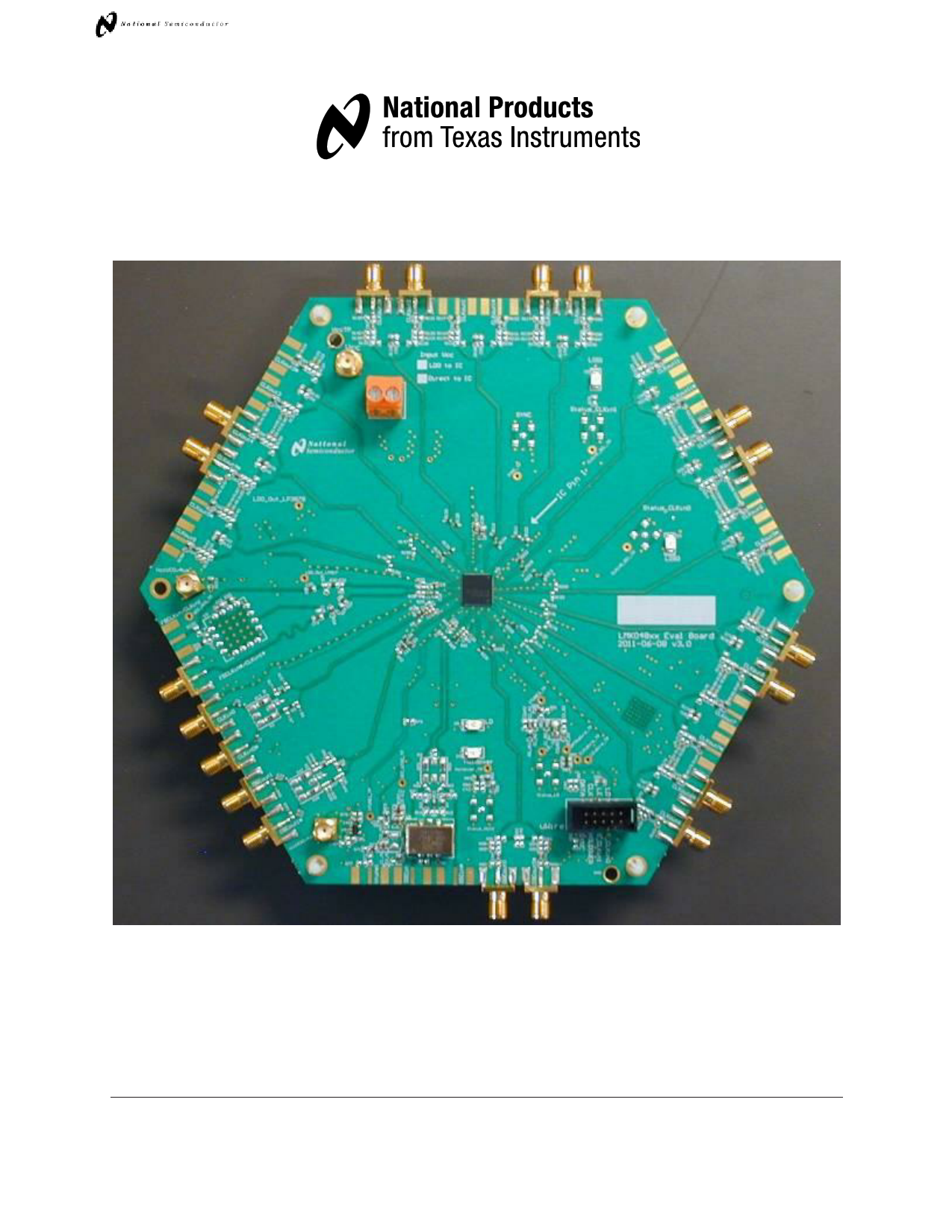
LMK048XX EVALUATION BOARD OPERATING INSTRUCTIONS
LMK04800 Family
Low-Noise Clock Jitter Cleaner with Dual Loop PLLs
LMK048xx Evaluation Board Operating Instructions
National Semiconductor Corporation
High Speed Products Division
Precision Timing Devices
January 2012
1
Free Datasheet http://www.Datasheet4U.com
1 page 
LMK048XX EVALUATION BOARD OPERATING INSTRUCTIONS
Quick Start
Full evaluation board instructions are downloadable from the LMK048xxB device product folder
at www.national.com.
1. Connect a power supply voltage of 5 V to the Vcc SMA connector. The onboard
LP3878-ADJ LDO regulator will output a low-noise 3.3 V supply to operate the device.
2. Connect a reference clock from a signal source to the CLKin1 SMA port. Use 122.88
MHz for default. The reference frequency depends on the device programming.
3. Connect the uWire header to a PC parallel port using the CodeLoader cable. A USB
interface is also available (search for “USB2UWIRE-IFACE” at www.national.com).
4. Program the device with a default mode using CodeLoader. Ctrl+L must be pressed at
least once to load all registers. Alternatively click menu “Keyboard Controls” “Load
Device”. CodeLoader can be downloaded from www.national.com/timing/software/.
5. Measurements may be made on an active output clock port via its SMA connector.
1 Power
5.0 V
(LDO)
CLCKLoKuot4u*t4
5.0 V
3.3 V
CLCKLoKuot1u0t1*0
Factory default is LDO is used.
Customer may reconfigure to
power LMK directly.
LMK048xx
CLKin1 CLCKLiKni0n0*
Reference clock from
signal generator or other
external source.
122.88 MHz
(Default)
2 Reference
uWire
header
CLCKLoKuot8u*t8
CCLLKKoouut6t6*
4
Program with CodeLoader
Be sure to press ‘Ctrl - L’
3 Parallel Port
Connector
Laptop or PC
Figure 1: Quick Start Diagram
5
Free Datasheet http://www.Datasheet4U.com
5 Page 
LMK048XX EVALUATION BOARD OPERATING INSTRUCTIONS
PLL Loop Filters and Loop Parameters
In jitter cleaning applications that use a cascaded or dual PLL architecture, the first PLL‟s
purpose is to substitute the phase noise of a low-noise oscillator (VCXO or crystal resonator) for
the phase noise of a “dirty” reference clock. The first PLL is typically configured with a narrow
loop bandwidth in order to minimize the impact of the reference clock phase noise. The reference
clock consequently serves only as a frequency reference rather than a phase reference.
The loop filters on the LMK048xx evaluation board are setup using the approach above. The
loop filter for PLL1 has been configured for a narrow loop bandwidth (< 100 Hz), while the loop
filter of PLL2 has been configured for a wide loop bandwidth (> 100 kHz). The specific loop
bandwidth values depend on the phase noise performance of the oscillator mounted on the board.
The following tables contain the parameters for PLL1 and PLL2 for each oscillator option.
National‟s Clock Design Tool can be used to optimize PLL phase noise/jitter for given
specifications. See: http://www.national.com/timing/software/.
PLL 1 Loop Filter
Table 4: PLL1 Loop Filter Parameters for Crystek 122.88 MHz VCXO
122.88 MHz VCXO PLL
Phase Margin
49˚ Kφ (Charge Pump)
Loop Bandwidth
12 Hz
Phase Detector Freq
VCO Gain
Reference Clock
Frequency
122.88 MHz
Output Frequency
Loop Filter
Components
C1_A1 = 100 nF
C2_A1 = 680 nF
100 uA
1.024 MHz
2.5 kHz/Volt
122.88 MHz (To PLL 2)
R2_A1 = 39 kΩ
Note: PLL Loop Bandwidth is a function of K , Kvco, N as well as loop components. Changing
K and N will change the loop bandwidth.
11
Free Datasheet http://www.Datasheet4U.com
11 Page | ||
| Páginas | Total 30 Páginas | |
| PDF Descargar | [ Datasheet LMK04800.PDF ] | |
Hoja de datos destacado
| Número de pieza | Descripción | Fabricantes |
| LMK04800 | Low-Noise Clock Jitter Cleaner | National Semiconductor |
| LMK04803 | LMK0480x Low-Noise Clock Jitter Cleaner with Dual Loop PLLs (Rev. K) | Texas Instruments |
| LMK04805 | LMK0480x Low-Noise Clock Jitter Cleaner with Dual Loop PLLs (Rev. K) | Texas Instruments |
| LMK04806 | LMK0480x Low-Noise Clock Jitter Cleaner with Dual Loop PLLs (Rev. K) | Texas Instruments |
| Número de pieza | Descripción | Fabricantes |
| SLA6805M | High Voltage 3 phase Motor Driver IC. |
Sanken |
| SDC1742 | 12- and 14-Bit Hybrid Synchro / Resolver-to-Digital Converters. |
Analog Devices |
|
DataSheet.es es una pagina web que funciona como un repositorio de manuales o hoja de datos de muchos de los productos más populares, |
| DataSheet.es | 2020 | Privacy Policy | Contacto | Buscar |