|
|
|
PDF 73M2901CE Data sheet ( Hoja de datos )
| Número de pieza | 73M2901CE | |
| Descripción | V.22bis Single Chip Modem | |
| Fabricantes | Teridian Semiconductor | |
| Logotipo | ||
Hay una vista previa y un enlace de descarga de 73M2901CE (archivo pdf) en la parte inferior de esta página. Total 27 Páginas | ||
|
No Preview Available !
Simplifying System Integration™
DS_2901CE_031
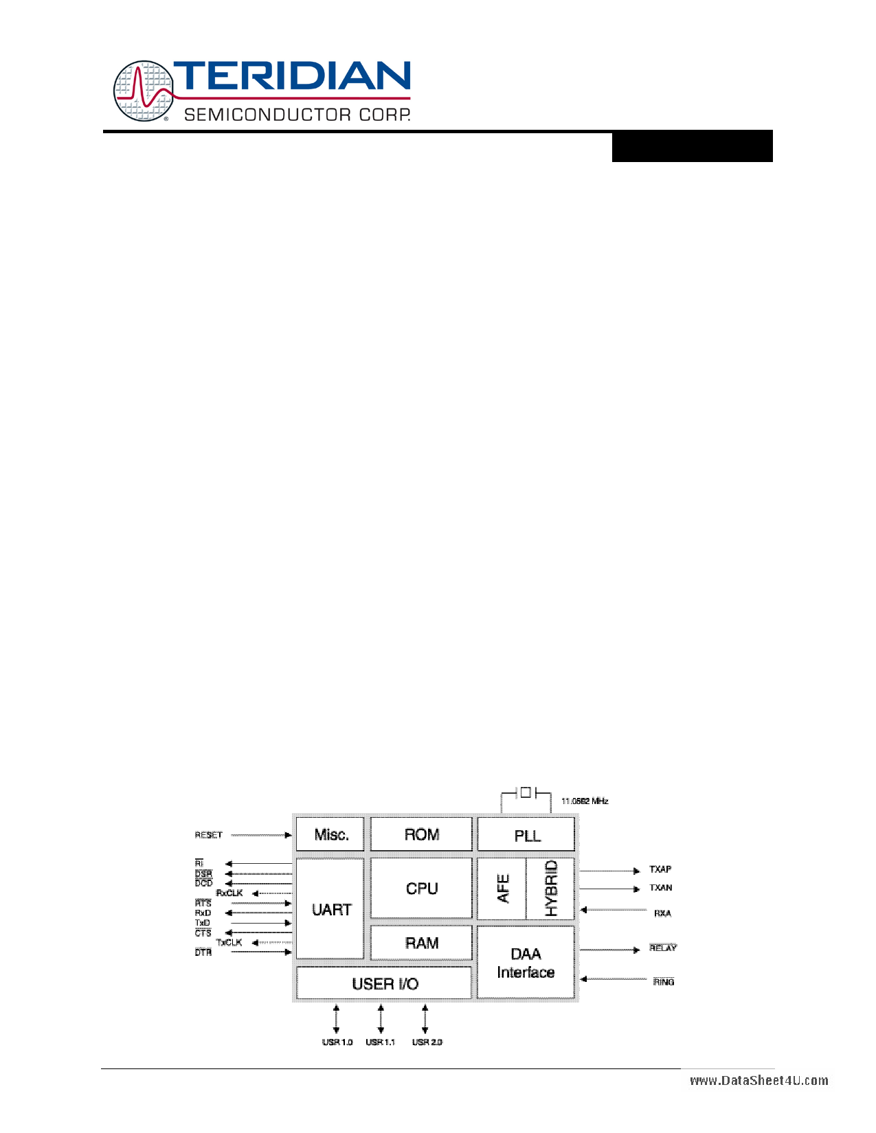
DESCRIPTION
The 73M2901CE low speed modem integrates a
data pump, controller, and analog front end in a
3.3 V device with a powerful "AT" command host
interface. The modem reduces external
component count/cost by incorporating many
features like parallel phone detect, Line-In-Use
and Ring detection in software without requiring
additional components.
The device is a "one chip fits all” solution for
applications including set-top boxes, point-of-sale
terminals, automatic teller machines, utility
meters, vending machines and smart card
readers.
Another distinctive feature of this device is pin
compatibility with Teridian’s flagship embedded
hard modems, the 73M2901CL, and the
73M1903 soft modem AFE. This offers
customers a cost effective method to design for
both hard or soft modem solutions in the same
system as a risk-free cost reduction path.
Complete support, modem reference designs
and error correction software are part of the
solution offered by Teridian. Our in-house
application engineering team is here to help
meet your international certification needs.
www.DataSheet4U.com
73M2901CE
V.22bis Single Chip Modem
DATA SHEET
January 2010
FEATURES
• True one chip solution for embedded systems
• As low as 9.5 mA operating with standby and
power down mode available
• Power supply operation from 3.6 V to 2.7 V
• Data modes and speeds:
V.22bis – 2400 bps
V.22/Bell212 – 1200 bps
V.21/Bell103 – 300 bps
V.23 – 1200/75 bps (with PAVI turnaround)
Bell202 – 1200 bps
Bell202/V23 1200 bps FDX 4-wire operation
• V.22/Bell 212A/V.22bis synchronous modes
• International Call Progress support:
FCC part 68, CTR21, JATE, etc.
• DTMF generation and detection
• Worldwide Caller ID capability
U.S. Type I and II support
• EIA 777A compliant
• SIA-2000 compliant
• SMS messaging support
• On chip hybrid driver
• Blacklisting capability
• Line-In-Use and Parallel Pick-Up (911) detection
with voltage or low cost energy detection method
• Incoming ring energy detection through CID
path; no optocoupler circuitry required
• Manufacturing Self Test capability
• Backward compatible with 73M2901CL
• Packaging: 32 lead QFN, 32-pin TQFP
Rev. 3.4
© 2010 Teridian Semiconductor Corporation
1
1 page 
DS_2901CE_031
73M2901CEwwDwa.DtaataSShheeete4Ut .com
RING is used to inform the 73M2901CE that the external DAA circuitry or ring energy detector has
detected a ring signal. It will go active when each “RING” message is sent on RXD.
In addition, sending any character on the TXD line also generates an internal interrupt.
1.5 Crystal Oscillator
The Teridian 73M2901CE single chip modem can use an external 11.0592 MHz reference clock or can
generate a clock using only a crystal and two capacitors. If an external clock is used, it should be applied
to the OSCIN pin.
1.5.1 Specifying a Crystal
The manufacturer of a crystal resonator verifies its frequency of oscillation in a test set-up, but to ensure
that the same frequency is obtained in the application, the circuit conditions must be the same.
The Teridian 73M2901CE modem requires a parallel mode (anti-resonant) crystal, the important
specifications of which are as follows:
Mode:
Frequency:
Frequency tolerance:
Temperature drift:
Load capacitance:
ESR:
Drive level:
Parallel (anti-resonant)
11.0592 MHz
±50 ppm at initial temperature
An additional ±50 ppm over full range
18 pF to 22 pF
75 Ω max
Less than 1 mW
The peak voltage level of the oscillator should be checked to assure it will not violate the maximum
voltage levels allowed on the oscillator pins. A resistor in series with the crystal can be used, if
necessary, to reduce the oscillator’s peak voltage levels.
Crystals with low ESRs may oscillate at higher than specified voltage levels.
1.6 Reset
A reset is accomplished by holding the RESET pin high. To ensure a proper power-on reset, the reset
pin must be held high for a minimum of 3 µs. At power on, the voltage at VPD, VPA, and RESET must
come up at the same time for a proper reset.
The signals DCD, CTS and DSR will be held inactive for 25 ms, acknowledging the reset operation, within
a 250 ms time window after the reset-triggering event. The 73M2901CE is ready for operation after the
250 ms window and/or after the signals DCD, CTS and DSR become active.
1.7 Asynchronous and Synchronous Serial Data Interface
The serial data interface consists of the TXD and RXD data paths (LSB shifted in and out first) and the
TXCLK and RXCLK serial synchronous clock outputs associated with the data pins; CTS/RTS flow
control; DCD, DSR and DTR. In asynchronous mode, the data is passed at the bit rate (tolerance is +1%,
-2.5%).
Rev. 3.4
5
5 Page 
DS_2901CE_031
73M2901CEwwDwa.DtaataSShheeete4Ut .com
4.6 DC Characteristics, Vcc = 3.3 V
(Vdd stands for VPD and VPA)
Parameter
Symbol Conditions
Input low voltage (except OSCIN) VIL
Input low voltage OSCIN
VIL
Input high voltage (except OSCIN) VIH
Input high voltage OSCIN
VIH
Output low voltage (except OSCOUT) VOL
IOL=4 mA
Output low voltage OSCOUT
VOLOSC IOL=3 mA
Output high voltage (except OSCOUT) VOH
IOH=-4 mA
Output high voltage OSCOUT
VOHOSC IOH=-3 mA
Input leakage current (except OSCIN) IIH
Vss<Vin<Vdd
Input leakage current OSCIN
IIH Vss<Vin<Vdd
Min
-0.5
-0.5
0.7 Vdd
0.7 Vdd
Vdd-0.45
Vdd-0.9
1
Nom
Max
0.8
0.2 Vdd
+5.5
Vdd+0.5
0.45
0.7
1
30
Unit
V
V
V
V
V
V
V
V
µA
µA
Parameter
VBG
VREF
TXAP to TXAN offset
Conditions
Vdd=3.3 V
Vdd=3.3 V
Vdd=3.3 V, steady state
4.6.1 DC Supply Current, VDD = 2.7 V (Battery EOL)
Parameter
Maximum power supply,
normal operation
Maximum power supply,
Idle mode
Maximum power supply,
Power Down mode
Symbol
IDD1
Conditions
30 pF/pin
IDD2
30 pF/pin
IDD3
30 pF/pin
4.6.2 DC Supply Current , VDD = 3.0 V
Parameter
Maximum power supply,
normal operation
Maximum power supply,
Idle mode
Maximum power supply,
Power Down mode
Symbol
IDD1
Conditions
30 pF/pin
IDD2
30 pF/pin
IDD3
30 pF/pin
Min Nom
1.19 1.25
1.19 1.25
Min Nom
9.5
900
Min Nom
10.6
1.1
Max
1.31
1.31
50
Max
10.5
1500
10
Max
11.9
1.7
10
Unit
V
V
mV
Unit
mA
µA
µA
Unit
mA
mA
µA
Rev. 3.4
11
11 Page | ||
| Páginas | Total 27 Páginas | |
| PDF Descargar | [ Datasheet 73M2901CE.PDF ] | |
Hoja de datos destacado
| Número de pieza | Descripción | Fabricantes |
| 73M2901CE | V.22bis Single Chip Modem | Teridian Semiconductor |
| 73M2901CL | V.22 BIS SINGLE CHIP MODEM | ETC |
| 73M2901CLIGT | V.22 BIS SINGLE CHIP MODEM | ETC |
| 73M2901CLIGV | V.22 BIS SINGLE CHIP MODEM | ETC |
| Número de pieza | Descripción | Fabricantes |
| SLA6805M | High Voltage 3 phase Motor Driver IC. |
Sanken |
| SDC1742 | 12- and 14-Bit Hybrid Synchro / Resolver-to-Digital Converters. |
Analog Devices |
|
DataSheet.es es una pagina web que funciona como un repositorio de manuales o hoja de datos de muchos de los productos más populares, |
| DataSheet.es | 2020 | Privacy Policy | Contacto | Buscar |