|
|
|
PDF X9314 Data sheet ( Hoja de datos )
| Número de pieza | X9314 | |
| Descripción | Single Digitally Controlled Potentiometer | |
| Fabricantes | Intersil Corporation | |
| Logotipo | ||
Hay una vista previa y un enlace de descarga de X9314 (archivo pdf) en la parte inferior de esta página. Total 9 Páginas | ||
|
No Preview Available !
®
Data Sheet
X9314
Terminal Voltages ±5V, 32 Taps, Log Taper
September 5, 2006
FN8178.2
Single Digitally Controlled Potentiometer
(XDCP™)
The Intersil X9314 is a solid state nonvolatile potentiometer and
is ideal for digitally controlled resistance trimming.
The X9314 is a resistor array composed of 31 resistive
elements. Between each element and at either end are tap
points accessible to the wiper element. The position of the
wiper element is controlled by the CS, U/D, and INC inputs.
The position of the wiper can be stored in nonvolatile
memory and then be recalled upon a subsequent power-up
operation.
The XDCP can be used as a three-terminal potentiometer or
as a two-terminal variable resistor in a wide variety of
applications including control, parameter adjustments, and
signal processing.
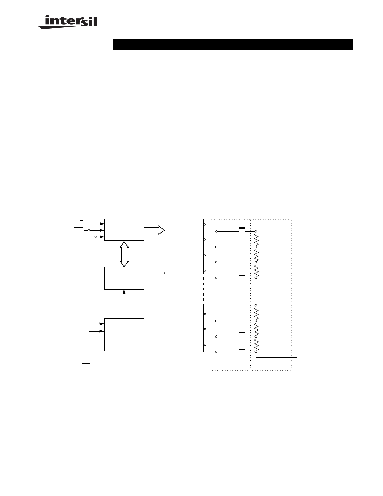
Block Diagram
Features
• Solid State Potentiometer
• 32 Taps
• 10kΩ End to End Resistance
• Three-Wire Up/Down Serial Interface
• Wiper Resistance, 40Ω Typical
• Nonvolatile Storage and Recall on Power-up of Wiper
Position Standby Current < 500µA Max (Total Package)
• VCC = 3V to 5.5V Operation
• 100 Year Data Retention
• Offered in 8 Ld MSOP, SOIC and PDIP Packages
• Pb-Free Plus Anneal Available (RoHS Compliant)
www.DataSheet4U.com
U/D 5-Bit
INC Up/Down
CS Counter
5-Bit
Nonvolatile
Memory
VCC
VSS
Store and
Recall
Control
Circuitry
31
30
29
28
One
of
Thirty-Two
Decoder
2
1
0
Transfer
Gates
VH/RH
Resistor
Array
VL/RL
VW/RW
1 CAUTION: These devices are sensitive to electrostatic discharge; follow proper IC Handling Procedures.
1-888-INTERSIL or 1-888-468-3774 | Intersil (and design) is a registered trademark of Intersil Americas Inc.
XDCP is a trademark of Intersil Americas Inc. Copyright Intersil Americas Inc. 2005, 2006. All Rights Reserved
All other trademarks mentioned are the property of their respective owners.
1 page 
X9314
DC Electrical Specifications (Over recommended operating conditions unless otherwise specified.)
SYMBOL
PARAMETER
TEST CONDITIONS
LIMITS
MIN TYP(2)
MAX
ICC VCC Active Current
ISB Standby Supply Current
ILI
VIH
VIL
CIN(3)
CS, INC, U/D Input Leakage Current
CS, INC, U/D Input HIGH Voltage
CS, INC, U/D Input LOW Voltage
CS, INC, U/D Input Capacitance
CS = VIL, U/D = VIL or VIH and
INC = 0.4V/2.4V @ max. tCYC
CS = VCC - 0.3V, U/D and INC = VSS or
VCC - 0.3V
VIN = VSS to VCC
VCC = 5V, VIN = VSS, TA = +25°C, f = 1MHz
2
-1
13
500
±10
VCC + 1
0.8
10
UNITS
mA
µA
µA
V
V
pF
Standard Parts
PART NUMBER
X9314W
MAXIMUM RESISTANCE
10kΩ
WIPER INCREMENTS
Log Taper
MINIMUM RESISTANCE
40Ω
NOTES:
2. Typical values are for TA = +25°C and nominal supply voltage.
3. This parameter is periodically sampled and not 100% tested.
Test Circuit #1
VH/RH
Test Point
VW/RW
VL/RL
Test Circuit #2
VH/RH
Test Point
VW/RW
Force
Current
VL/RL
Circuit #3 SPICE Macromodel
Macro Model
RTOTAL
RH CL RL
CH CW 10pF
10pF
25pF
RW
A.C. Conditions of Test
INPUT PULSE LEVELS
Input rise and fall times
Input reference levels
0V to 3V
10ns
1.5V
Mode Selection
CS INC U/D
LH
LL
HX
HXX
LX
MODE
Wiper up
Wiper down
Store wiper position
Standby
No store, return to standby
SYMBOL TABLE
WAVEFORM
INPUTS
Must be
steady
May change
from Low to
High
May change
from High to
Low
Don’t Care:
Changes
Allowed
N/A
OUTPUTS
Will be
steady
Will change
from Low to
High
Will change
from High to
Low
Changing:
State Not
Known
Center Line
is High
Impedance
5 FN8178.2
September 5, 2006
5 Page | ||
| Páginas | Total 9 Páginas | |
| PDF Descargar | [ Datasheet X9314.PDF ] | |
Hoja de datos destacado
| Número de pieza | Descripción | Fabricantes |
| X9312 | E2POT Nonvolatile Digital Potentiometer | Xicor |
| X9312 | Terminal Voltage 0V to 15V | Intersil Corporation |
| X9313 | E2POT Nonvolatile Digital Potentiometer | Xicor |
| X9313 | Digitally Controlled Potentiometer | Intersil Corporation |
| Número de pieza | Descripción | Fabricantes |
| SLA6805M | High Voltage 3 phase Motor Driver IC. |
Sanken |
| SDC1742 | 12- and 14-Bit Hybrid Synchro / Resolver-to-Digital Converters. |
Analog Devices |
|
DataSheet.es es una pagina web que funciona como un repositorio de manuales o hoja de datos de muchos de los productos más populares, |
| DataSheet.es | 2020 | Privacy Policy | Contacto | Buscar |