X40411 반도체 회로 부품 판매점
(X40410 - X40415) Dual Voltage Monitor
|
|
|
Intersil Corporation |

®
Data Sheet
X40410, X40411, X40414, X40415
4kbit EEPROM
March 28, 2005
FN8116.0
Dual Voltage Monitor with Integrated CPU
Supervisor
FEATURES
• Dual voltage detection and reset assertion
—Standard reset threshold settings
See Selection table on page 2.
—Adjust low voltage reset threshold voltages
using special programming sequence
—Reset signal valid to VCC = 1V
—Monitor three voltages or detect power fail
• Independent Core Voltage Monitor (V2MON)
• Fault detection register
• Selectable power-on reset timeout (0.05s,
0.2s, 0.4s, 0.8s)
• Selectable watchdog timer interval (25ms,
200ms,1.4s, off)
• Low power CMOS
—25µA typical standby current, watchdog on
—6µA typical standby current, watchdog off
• 4Kbits of EEPROM
—16 byte page write mode
—5ms write cycle time (typical)
www.DataSheet4U.com
• Built-in inadvertent write protection
—Power-up/power-down protection circuitry
—Block lock protect none or 1/2 of EEPROM
• 400kHz 2-wire interface
• 2.7V to 5.5V power supply operation
BLOCK DIAGRAM
• Available packages
—8-lead SOIC, TSSOP
• Monitor Voltages: 5V to 0.9V
• Memory Security
• Independent Core Voltage Monitor
APPLICATIONS
• Communication Equipment
—Routers, Hubs, Switches
—Disk Arrays, Network Storage
• Industrial Systems
—Process Control
—Intelligent Instrumentation
• Computer Systems
— Computers
—Network Servers
DESCRIPTION
The X40410/11/14/15 combines power-on reset con-
trol, watchdog timer, supply voltage supervision, and
secondary voltage supervision, and Block Lock™ pro-
tect serial EEPROM in one package. This combination
lowers system cost, reduces board space require-
ments, and increases reliability.
Applying voltage to VCC activates the power-on reset
circuit which holds RESET/RESET active for a period of
time. This allows the power supply and system oscilla-
SDA
SCL
VCC
(V1MON)
V2MON
Data
Register
Command
Decode Test
& Control
Logic
Threshold
Reset Logic
Fault Detection
Register
Status
Register
EEPROM
Array
Watchdog Timer
and
Reset Logic
User Programmable
VTRIP1
User Programmable
VTRIP2
+
-
VCC or
+ V2MON
Power-on,
Low Voltage
Reset
Generation
-
*X40410/11= V2MON*
X40414/15 = VCC
WDO
RESET
X40410/14
RESET
X40411/15
V2FAIL
1
CAUTION: These devices are sensitive to electrostatic discharge; follow proper IC Handling Procedures.
1-888-INTERSIL or 1-888-352-6832 | Intersil (and design) is a registered trademark of Intersil Americas Inc.
Copyright Intersil Americas Inc. 2005. All Rights Reserved
All other trademarks mentioned are the property of their respective owners.
X40410, X40411, X40414, X40415
Low VCC detection circuitry protects the user’s system
from low voltage conditions, resetting the system when
VCC falls below the minimum VTRIP1 point. RESET/RE-
SET is active until VCC returns to proper operating level
and stabilizes. A second voltage monitor circuit tracks
the unregulated supply to provide a power fail warning
or monitors different power supply voltage. Three com-
mon low voltage combinations are available, however,
Intersil’s unique circuits allows the threshold for either
voltage monitor to be reprogrammed to meet special
needs or to fine-tune the threshold for applications re-
quiring higher precision.
The Watchdog Timer provides an independent protec-
tion mechanism for microcontrollers. When the micro-
controller fails to restart a timer within a selectable
time out interval, the device activates the WDO signal.
The user selects the interval from three preset values.
Once selected, the interval does not change, even
after cycling the power.
The memory portion of the device is a CMOS Serial
EEPROM array with Intersil’s Block Lock protection.
The array is internally organized as x 8. The device
features a 2-wire interface and software protocol
allowing operation on an I2C® bus.
The device utilizes Intersil’s proprietary Direct Write™
cell, providing a minimum endurance of 100,000
cycles and a minimum data retention of 100 years.
Triple Voltage Monitors
Device
X4040/11
-A
-B
-C
X40414/15
-A
-B
-C
Expected System Voltages
5V; 3V or 3.3V
5V; 3V
3V; 3.3V; 1.8V
3V; 3.3V; 1.5V
3V; 1.5V
3V or 3.3V; 1.1 or 1.2V
Vtrip1(V)
2.0–4.75*
4.55–4.65*
4.35–4.45*
2.85–2.95*
2.0–4.75*
2.85–2.95*
2.55–2.65*
2.85–2.95*
*Voltage monitor requires VCC to operation. Others are independent of VCC.
Vtrip2(V)
1.70–4.75
2.85–2.95
2.55–2.65
1.65–1.75
0.90–3.50*
1.25–1.35*
1.25–1.35*
0.95–1.05*
POR (system)
RESET = X40410
RESET = X40411
RESET = X40414
RESET = X40415
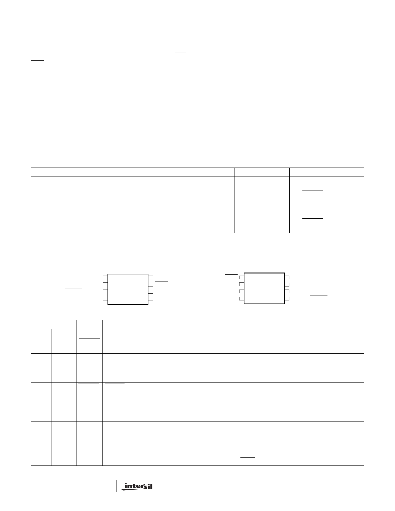
PIN CONFIGURATION
X40410/14, X40411/15
8-Pin SOIC
V2FAIL 1
V2MON 2
8 VCC
7 WDO
RESET/RESET
VSS
3
4
6 SCL
5 SDA
X40410/14, X40411/15
8-Pin TSSOP
WDO
VCC
V2FAIL
V2MON
1
2
3
4
8 SCL
7 SDA
6 VSS
5 RESET/RESET
PIN DESCRIPTION
Pin
SOIC TSSOP Name
Function
1 3 V2FAIL V2 Voltage Fail Output. This open drain output goes LOW when V2MON is less than VTRIP2 and
goes HIGH when V2MON exceeds VTRIP2. There is no power-up reset delay circuitry on this pin.
2 4 V2MON V2 Voltage Monitor Input. When the V2MON input is less than the VTRIP2 voltage, V2FAIL goes
LOW. This input can monitor an unregulated power supply with an external resistor divider or can
monitor a second power supply with no external components. Connect V2MON to VSS or VCC when
not used.The V2MON comparator is supplied by V2MON (X40410/11) or by VCC Input (X40414/15).
3 5 RESET/ RESET Output. (X40411/15) This is an active LOW, open drain output which goes active whenever
RESET VCC falls below VTRIP1. It will remain active until VCC rises above VTRIP1 and for the tPURST thereafter.
RESET Output. (X40410/14) This is an active HIGH CMOS output which goes active whenever VCC
falls below VTRIP1. It will remain active until VCC rises above VTRIP1 and for the tPURST thereafter.
4 6 VSS Ground
5 7 SDA Serial Data. SDA is a bidirectional pin used to transfer data into and out of the device. It has an open
drain output and may be wire ORed with other open drain or open collector outputs. This pin requires
a pull up resistor and the input buffer is always active (not gated).
Watchdog Input. A HIGH to LOW transition on the SDA (while SCL is toggled from HIGH to
LOW and followed by a stop condition) restarts the Watchdog timer. The absence of this transi-
tion within the watchdog time out period results in WDO going active.
2 FN8116.0
March 28, 2005
|
PDF 파일 내의 페이지 : 총 24 페이지
제조업체: Intersil Corporation
( intersil )
X40411 data
데이터시트 다운로드 :
[ X40411.PDF ]
[ X40411 다른 제조사 검색 ]
국내 전력반도체 판매점
상호 : 아이지 인터내셔날
전화번호 : 051-319-2877
[ 홈페이지 ]
IGBT, TR 모듈, SCR, 다이오드모듈, 각종 전력 휴즈
( IYXS, Powerex, Toshiba, Fuji, Bussmann, Eaton )
전력반도체 문의 : 010-3582-2743
관련 데이터시트
X40410
(X40410 - X40415) Dual Voltage Monitor - Intersil Corporation

X40411
(X40410 - X40415) Dual Voltage Monitor - Intersil Corporation
X40414
(X40410 - X40415) Dual Voltage Monitor - Intersil Corporation
X40415
(X40410 - X40415) Dual Voltage Monitor - Intersil Corporation