|
|
|
PDF NIS5102 Data sheet ( Hoja de datos )
| Número de pieza | NIS5102 | |
| Descripción | High Side SMART HotPlug IC/Inrush Limiter/Circuit Breaker | |
| Fabricantes | ON Semiconductor | |
| Logotipo | ||
Hay una vista previa y un enlace de descarga de NIS5102 (archivo pdf) en la parte inferior de esta página. Total 14 Páginas | ||
|
No Preview Available !
www.DataSheet4U.com
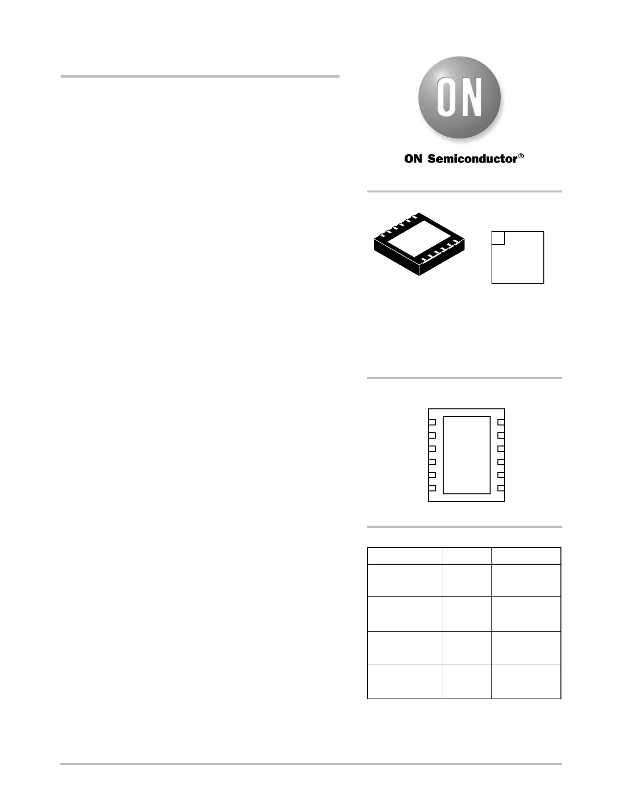
NIS5102
High Side
SMART HotPlugE IC/Inrush
Limiter/Circuit Breaker
The NIS5102 is a controller/FET IC that saves design time and
reduces the number of components required for a complete hot swap
application. It is designed for +12 V applications.
This chip includes a time delay for sequencing applications. It has a
dual function OVLO pin that allows multiple units to be ganged
together for simultaneous turn−on and shutdown, allowing units to be
operated in parallel. It allows for user selectable undervoltage and
overvoltage lockout levels. Its unique current limit circuit allows for
adjustable current limit levels with no external power resistor. An
internal temperature limiting circuit greatly increases the reliability of
this device.
Features
• Integrated Power Device
• Power Device Thermally Protected
• No External Current Shunt Required
• Simultaneous Shutdown and Startup for Parallel Operation
• Enable/Timer Pin
• Power Good
• 9.0 to 18 V Input Range
• 10 mW
• Main/Mirror MOSFET Current Ratio 1000:1
• Pb−Free Packages are Available
Typical Applications
• High Availability Systems
• Electronic Circuit Breaker
• 12 V Distributed Architecture
http://onsemi.com
ÎÎÎÎ
MARKING
DIAGRAM
1
5102QPxH
AWLYWWG
9x9 MM, 12 PIN PLLP
CASE 488AB
x = 1 or 2
A = Assembly Location
WL = Wafer Lot
Y = Year
WW = Work Week
G = Pb−Free
PIN CONNECTIONS
12 1
11 2
10 13 3
94
85
76
(Bottom View)
ORDERING INFORMATION
Device
Package
Shipping†
NIS5102QP1HT1 9x9 mm 1500/Tape & Reel
(Latchoff)
12 Pin PLLP
NIS5102QP1HT1G 12 Pin PLLP 1500/Tape & Reel
(Latchoff)
(Pb−Free)
NIS5102QP2HT1 9x9 mm 1500/Tape & Reel
(Auto−Retry)
12 Pin PLLP
NIS5102QP2HT1G 12 Pin PLLP 1500/Tape & Reel
(Auto−Retry)
(Pb−Free)
†For information on tape and reel specifications,
including part orientation and tape sizes, please
refer to our Tape and Reel Packaging Specifications
Brochure, BRD8011/D.
© Semiconductor Components Industries, LLC, 2006
October, 2006 − Rev. 5
1
Publication Order Number:
NIS5102/D
1 page 
NIS5102
TYPICAL PERFORMANCE CURVES
(TA = 25°C unless otherwise noted)
14
13
Turn−on
12
11
Turn−off
10
9
8
200 300 400 500 600 700 800 900 1000
RUVLO (kW)
Figure 3. UVLO Adjustment
19
18 Turn−off
17
16 Turn−on
15
14
13
12
11
10
9
100 200 300 400 500 600 700 800 900 1000
ROVLO (kW)
Figure 4. OVLO Adjustment
100 10
Vin = 12 V
Rext_ILimit = 100 W
10
Overload
1
Short Circuit
1 0.1
0.1
10
100
RILmit (W)
Figure 5. Current Limit Adjustment
0.01
1000
10
100
1000
10000
LOAD CAPACITANCE (mF)
Figure 6. Load Capacitance vs. Output di/dt
105
Device Reaching
95 Thermal Shutdown
85
75
1/4 sq in copper area
65
1 sq in copper area
55 2 sq in copper area
45
35
25
1.0 3.0 5.0 7.0 9.0 11
13
CONTINUOUS CURRENT, A
Figure 7. Continuous Current vs. Case Temperature
(Test performed on a double−sided copper board, 1 oz)
16
14
12
10
8
6
4
2
0
−40 −25 −10 5 20 35 50 65 80 95 110 125
TJ, JUNCTION TEMPERATURE, (°C)
Figure 8. Typical RDS(on) vs. Junction
Temperature
http://onsemi.com
5
5 Page 
NIS5102
VCC
ROVLO
300 k
OVLO
200 k 2 M
7V
Source
Ground
Figure 19. Equivalent Overvoltage Lockout Circuit
The theoretical equation for the OVLO turn−on voltage is:
ROVLO
(KW)
+
300 Vin * 2100
21.8 * Vin
The OVLO trip point voltage calculated through the
theoretical formula may show small variations with respect
to Figure 4, therefore it is recommended to use the formulas
gotten from the OVLO characterization, which are shown
below:
ROVLO (kW) + e [(OVLO ) 5.2)ń3.46]; for TJ + 25°C
where “OVLO” is the desired overvoltage lockout value,
and ROVLO is the programming resistor from the OVLO pin
to the VCC pin.
To reduce nuisance tripping due to transients and noise
spikes, a capacitor may be added from the OVLO pin to
ground. This will create a low pass filter with a cutoff
frequency of f. The required capacitance on this pin is:
COVLO
+
[1
)
(8.83 E−6 · ROVLO)]
2p · f · ROVLO
This pin is also used as a common shutdown pin. In this
mode, if this pin is pulled to ground, it will shutdown the chip
and all chips connected to its OVLO pin.
The OVLO pin has an internal switch to ground that will
pull it low, whenever the device is disabled due to any fault
other than an Overvoltage condition. An enable pin
shutdown is not considered a fault and will not cause a
common shutdown. This feature allows multiple units to
turn on and off simultaneously by tying the OVLO pins
together in parallel. This can be used for operating several
hot plug devices in parallel, or for use with separate loads,
when all devices need to startup and shutdown
simultaneously.
Temperature Limit
The temperature limit circuit senses the temperature of the
Power FET and removes the gate drive if the maximum level
is exceeded. For the auto−retry device, there is a nominal
hysteresis of 40°C for this circuit. After a thermal shutdown,
the device will automatically restart when the temperature
drops to a safe level as determined by the hysteresis. The
latching thermal circuit can be reset either by recycling the
input power, or by toggling the enable signal.
Current Limit
An external resistor from the current limit pin to the source
pins set the level at which the device will limit the current.
The plot of resistance vs. current limit includes two curves,
one for short circuit and one for overload.
A short circuit condition is one in which the SENSEFET
is not fully enhanced, and is therefore in a high impedance
mode of operation. In this case there are many hundreds of
millivolts across the drain to source pins of the SENSEFET.
This occurs when the output sees a very low impedance short
as well as when the capacitor is charging at turn on. In both
cases there are several volts or more across the FET.
An overload condition is one in which the SENSEFET is
still fully enhanced and the drain to source voltage is the
product of the drain current and the on resistance of the FET.
The sense voltage out of the SENSEFET has a different
relation to the drain current in these two conditions. The
difference in current limit levels for these two cases is called
DI, where:
DI + VrefńRDSon
http://onsemi.com
11
11 Page | ||
| Páginas | Total 14 Páginas | |
| PDF Descargar | [ Datasheet NIS5102.PDF ] | |
Hoja de datos destacado
| Número de pieza | Descripción | Fabricantes |
| NIS5101 | SMART HotPlug IC/Inrush Limiter/Circuit Breaker | ON Semiconductor |
| NIS5102 | High Side SMART HotPlug IC/Inrush Limiter/Circuit Breaker | ON Semiconductor |
| Número de pieza | Descripción | Fabricantes |
| SLA6805M | High Voltage 3 phase Motor Driver IC. |
Sanken |
| SDC1742 | 12- and 14-Bit Hybrid Synchro / Resolver-to-Digital Converters. |
Analog Devices |
|
DataSheet.es es una pagina web que funciona como un repositorio de manuales o hoja de datos de muchos de los productos más populares, |
| DataSheet.es | 2020 | Privacy Policy | Contacto | Buscar |