|
|
|
PDF NGB18N40CLBT4 Data sheet ( Hoja de datos )
| Número de pieza | NGB18N40CLBT4 | |
| Descripción | N-Channel D2PAK | |
| Fabricantes | ON Semiconductor | |
| Logotipo | ||
Hay una vista previa y un enlace de descarga de NGB18N40CLBT4 (archivo pdf) en la parte inferior de esta página. Total 10 Páginas | ||
|
No Preview Available !
www.DataSheet4U.com
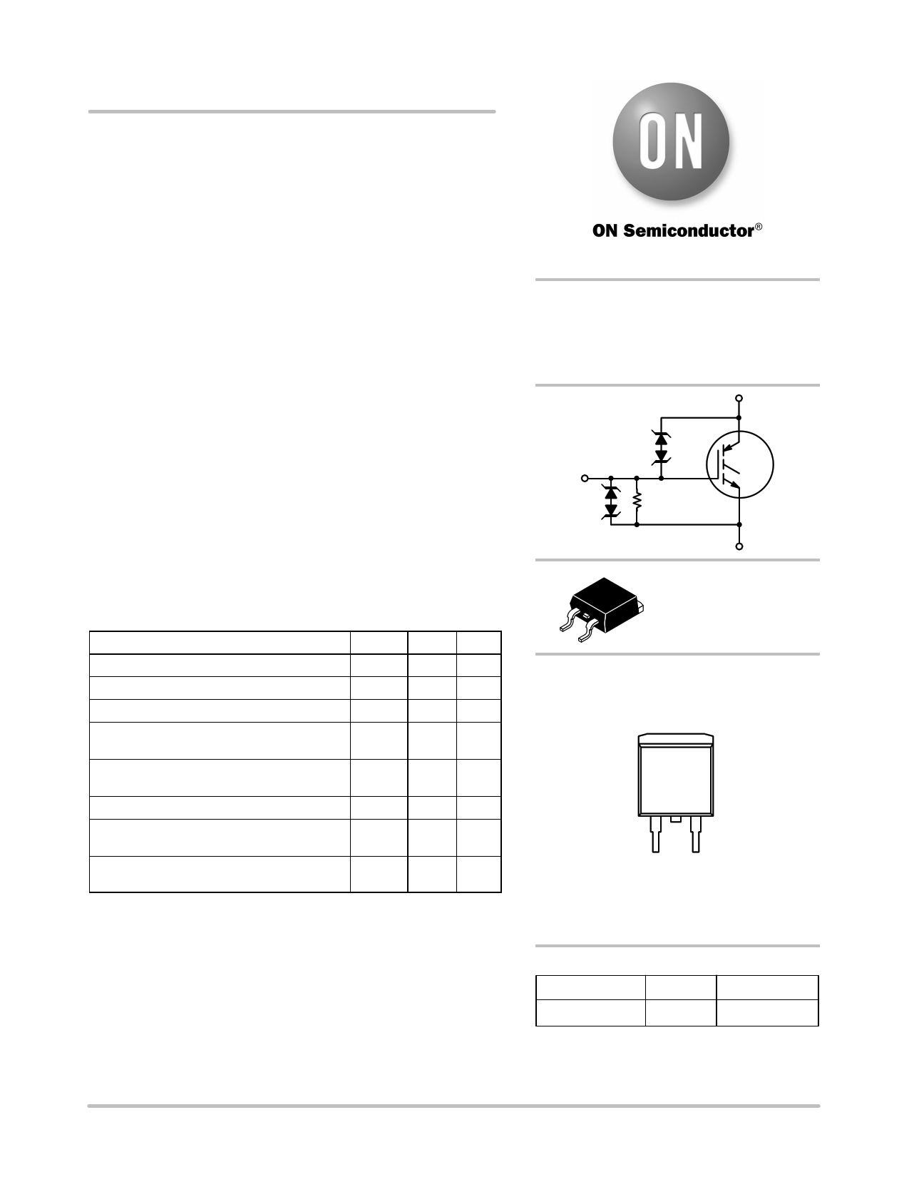
NGB18N40CLBT4
Ignition IGBT
18 Amps, 400 Volts
N−Channel D2PAK
This Logic Level Insulated Gate Bipolar Transistor (IGBT) features
monolithic circuitry integrating ESD and Over−Voltage clamped
protection for use in inductive coil drivers applications. Primary uses
include Ignition, Direct Fuel Injection, or wherever high voltage and
high current switching is required.
• Ideal for Coil−on−Plug Applications
• Gate−Emitter ESD Protection
• Temperature Compensated Gate−Collector Voltage Clamp Limits
Stress Applied to Load
• Integrated ESD Diode Protection
• New Design Increases Unclamped Inductive Switching (UIS) Energy
Per Area
• Low Threshold Voltage to Interface Power Loads to Logic or
Microprocessor Devices
• Low Saturation Voltage
• High Pulsed Current Capability
• Integrated Gate−Emitter Resistor (RGE)
• Emitter Ballasting for Short−Circuit Capability
MAXIMUM RATINGS (TJ = 25°C unless otherwise noted)
Rating
Symbol Value
Unit
Collector−Emitter Voltage
Collector−Gate Voltage
Gate−Emitter Voltage
Collector Current−Continuous
@ TC = 25°C − Pulsed
VCES
VCER
VGE
IC
430 VDC
430 VDC
18 VDC
18 ADC
50 AAC
ESD (Human Body Model)
R = 1500 W, C = 100 pF
ESD
kV
8.0
ESD (Machine Model) R = 0 W, C = 200 pF
ESD 800 V
Total Power Dissipation @ TC = 25°C
Derate above 25°C
PD 115 Watts
0.77 W/°C
Operating and Storage Temperature Range
TJ, Tstg −55 to
+175
°C
Maximum ratings are those values beyond which device damage can occur.
Maximum ratings applied to the device are individual stress limit values (not
normal operating conditions) and are not valid simultaneously. If these limits are
exceeded, device functional operation is not implied, damage may occur and
reliability may be affected.
http://onsemi.com
18 AMPS
400 VOLTS
VCE(on) 3 2.0 V @
IC = 10 A, VGE . 4.5 V
C
G
RGE
E
D2PAK
CASE 418B
STYLE 4
MARKING
DIAGRAM
4
Collector
GB
18N40B
YWW
13
Gate
2
Emitter
Collector
GB18N40B = NGB18N40CLB
Y = Year
WW = Work Week
ORDERING INFORMATION
Device
Package
Shipping†
NGB18N40CLBT4 D2PAK 800/Tape & Reel
†For information on tape and reel specifications,
including part orientation and tape sizes, please
refer to our Tape and Reel Packaging Specifications
Brochure, BRD8011/D.
Semiconductor Components Industries, LLC, 2005
March, 2005 − Rev. 1
1
Publication Order Number:
NGB18N40CLB/D
1 page 
NGB18N40CLBT4
TYPICAL ELECTRICAL CHARACTERISTICS (unless otherwise noted)
60
VGE = 10 V
50
5V
40 4.5 V
30 TJ = 25°C
20
10
4V
3.5 V
3V
2.5 V
0
0 1 2 34 5 678
VCE, COLLECTOR TO EMITTER VOLTAGE (VOLTS)
Figure 1. Output Characteristics
60
VGE = 10 V
50
40
TJ = −40°C
30
5V
4.5 V
4V
3.5 V
20
3V
10
2.5 V
0
0 1 2 34 5 678
VCE, COLLECTOR TO EMITTER VOLTAGE (VOLTS)
Figure 2. Output Characteristics
60
50
40
TJ = 150°C
30
20
10
VGE = 10 V
5V
4.5 V
4V
3.5 V
3V
2.5 V
0
0 1 2 34 5 678
VCE, COLLECTOR TO EMITTER VOLTAGE (VOLTS)
Figure 3. Output Characteristics
60
55
50
45
40
35
30
25
20
15
10
5
0
0
VCE = 10 V
TJ = −40°C
1 23 4
TJ = 150°C
TJ = 25°C
5 6 78
VGE, GATE TO EMITTER VOLTAGE (VOLTS)
Figure 4. Transfer Characteristics
4.0
3.5 VGE = 5 V
3.0
2.5
2.0
1.5
1.0
IC = 25 A
IC = 20 A
IC = 15 A
IC = 10 A
IC = 5 A
0.5
0.0
−50 −25
0
25 50 75 100 125 150
TJ, JUNCTION TEMPERATURE (°C)
Figure 5. Collector−to−Emitter Saturation
Voltage versus Junction Temperature
3
2.5
IC = 15 A
2 IC = 10 A
1.5 IC = 5 A
1
TJ = 25°C
0.5
0
3 4 5 6 7 8 9 10
GATE−TO−EMITTER VOLTAGE (VOLTS)
Figure 6. Collector−to−Emitter Voltage versus
Gate−to−Emitter Voltage
http://onsemi.com
5
5 Page | ||
| Páginas | Total 10 Páginas | |
| PDF Descargar | [ Datasheet NGB18N40CLBT4.PDF ] | |
Hoja de datos destacado
| Número de pieza | Descripción | Fabricantes |
| NGB18N40CLBT4 | N-Channel D2PAK | ON Semiconductor |
| Número de pieza | Descripción | Fabricantes |
| SLA6805M | High Voltage 3 phase Motor Driver IC. |
Sanken |
| SDC1742 | 12- and 14-Bit Hybrid Synchro / Resolver-to-Digital Converters. |
Analog Devices |
|
DataSheet.es es una pagina web que funciona como un repositorio de manuales o hoja de datos de muchos de los productos más populares, |
| DataSheet.es | 2020 | Privacy Policy | Contacto | Buscar |