|
|
|
PDF ST62P15C Data sheet ( Hoja de datos )
| Número de pieza | ST62P15C | |
| Descripción | (ST62P15C / ST62P25C) 8-BIT MCU | |
| Fabricantes | ST Microelectronics | |
| Logotipo | ||
Hay una vista previa y un enlace de descarga de ST62P15C (archivo pdf) en la parte inferior de esta página. Total 30 Páginas | ||
|
No Preview Available !
ST6215C/ST6225C
8-BIT MCUs WITH A/D CONVERTER,
TWO TIMERS, OSCILLATOR SAFEGUARD & SAFE RESET
s Memories
– 2K or 4K bytes Program memory (OTP,
EPROM, FASTROM or ROM) with read-out
protection
– 64 bytes RAM
s Clock, Reset and Supply Management
– Enhanced reset system
– Low Voltage Detector (LVD) for Safe Reset
– Clock sources: crystal/ceramic resonator or
RC network, external clock, backup oscillator
(LFAO)
– Oscillator Safeguard (OSG)
– 2 Power Saving Modes: Wait and Stop
s Interrupt Management
– 4 interrupt vectors plus NMI and RESET
– 20 external interrupt lines (on 2 vectors)
– 1 external non-interrupt line
s 20 I/O Ports
– 20 multifunctional bidirectional I/O lines
– 16 alternate function lines
– 4 high sink outputs (20mA)
s 2 Timers
– Configurable watchdog timer
– 8-bit timer/counter with a 7-bit prescaler
s Analog Peripheral
– 8-bit ADC with 16 input channels
s Instruction Set
– 8-bit data manipulation
– 40 basic instructions
– 9 addressing modes
– Bit manipulation
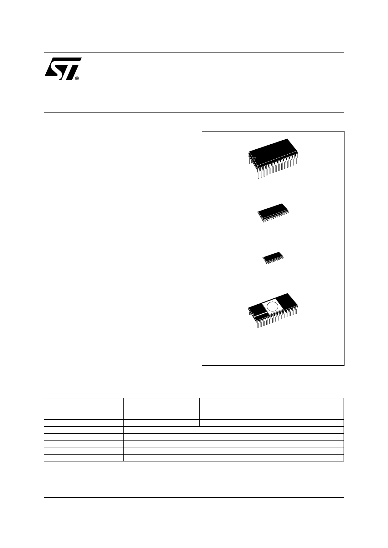
PDIP28
S028
SS0P28
CDIP28W
(See Section 12.5 for Ordering Information)
s Development Tools
– Full hardware/software development package
Device Summary
Features
Program memory - bytes
RAM - bytes
Operating Supply
Clock Frequency
Operating Temperature
Packages
ST62T15C(OTP)
ST6215C(ROM)
ST62P15C(FASTROM)
ST62T25C(OTP)
ST6225C(ROM)
ST62P25C(FASTROM
2K
64
3.0V to 6V
8MHz Max
-40°C to +125°C
PDIP28 / SO28 / SSOP28
4K
ST62E25C(EPROM)
CDIP28W
July 2001
Rev. 3.2
1/105
1
1 page 
Table of Contents
11.11 8-BIT ADC CHARACTERISTICS . . . . . . . . . . . . . . . . . . . . . . . . . . . . . . . . . . . . . . . . . . 89
12 GENERAL INFORMATION . . . . . . . . . . . . . . . . . . . . . . . . . . . . . . . . . . . . . . . . . . . . . . . . . . . . 91
12.1 PACKAGE MECHANICAL DATA . . . . . . . . . . . . . . . . . . . . . . . . . . . . . . . . . . . . . . . . . . 91
12.2 THERMAL CHARACTERISTICS . . . . . . . . . . . . . . . . . . . . . . . . . . . . . . . . . . . . . . . . . . 93
12.3 SOLDERING AND GLUEABILITY INFORMATION . . . . . . . . . . . . . . . . . . . . . . . . . . . . . 94
12.4 PACKAGE/SOCKET FOOTPRINT PROPOSAL . . . . . . . . . . . . . . . . . . . . . . . . . . . . . . . 95
12.5 ORDERING INFORMATION . . . . . . . . . . . . . . . . . . . . . . . . . . . . . . . . . . . . . . . . . . . . . . 96
12.6 TRANSFER OF CUSTOMER CODE . . . . . . . . . . . . . . . . . . . . . . . . . . . . . . . . . . . . . . . 97
12.6.1FASTROM Version . . . . . . . . . . . . . . . . . . . . . . . . . . . . . . . . . . . . . . . . . . . . . . . . . 97
12.6.2ROM Version . . . . . . . . . . . . . . . . . . . . . . . . . . . . . . . . . . . . . . . . . . . . . . . . . . . . . . 98
13 DEVELOPMENT TOOLS . . . . . . . . . . . . . . . . . . . . . . . . . . . . . . . . . . . . . . . . . . . . . . . . . . . . 100
14 ST6 APPLICATION NOTES . . . . . . . . . . . . . . . . . . . . . . . . . . . . . . . . . . . . . . . . . . . . . . . . . . 102
15 SUMMARY OF CHANGES . . . . . . . . . . . . . . . . . . . . . . . . . . . . . . . . . . . . . . . . . . . . . . . . . . . 104
16 TO GET MORE INFORMATION . . . . . . . . . . . . . . . . . . . . . . . . . . . . . . . . . . . . . . . . . . . . . . . 104
5/105
1
5 Page 
ST6215C/ST6225C
MEMORY MAP (Cont’d)
3.1.2 Program Space
Program Space comprises the instructions to be
executed, the data required for immediate ad-
dressing mode instructions, the reserved factory
test area and the user vectors. Program Space is
addressed via the 12-bit Program Counter register
(PC register). Thus, the MCU is capable of ad-
dressing 4K bytes of memory directly.
3.1.3 Readout Protection
The Program Memory in OTP or EPROM devices
can be protected against external readout of mem-
ory by setting the Readout Protection bit in the op-
tion byte (Section 3.3 on page 16).
In the EPROM parts, Readout Protection option
can be desactivated only by U.V. erasure that also
results in the whole EPROM context being erased.
Note: Once the Readout Protection is activated, it
is no longer possible, even for STMicroelectronics,
to gain access to the OTP contents. Returned
parts can therefore not be accepted if the Readout
Protection bit is set.
3.1.4 Data Space
Data Space accommodates all the data necessary
for processing the user program. This space com-
prises the RAM resource, the processor core and
peripheral registers, as well as read-only data
such as constants and look-up tables in OTP/
EPROM.
3.1.4.1 Data ROM
All read-only data is physically stored in program
memory, which also accommodates the Program
Space. The program memory consequently con-
tains the program code to be executed, as well as
the constants and look-up tables required by the
application.
The Data Space locations in which the different
constants and look-up tables are addressed by the
processor core may be thought of as a 64-byte
window through which it is possible to access the
read-only data stored in OTP/EPROM.
3.1.4.2 Data RAM
The data space includes the user RAM area, the
accumulator (A), the indirect registers (X), (Y), the
short direct registers (V), (W), the I/O port regis-
ters, the peripheral data and control registers, the
interrupt option register and the Data ROM Win-
dow register (DRWR register).
3.1.5 Stack Space
Stack space consists of six 12-bit registers which
are used to stack subroutine and interrupt return
addresses, as well as the current program counter
contents.
11/105
1
11 Page | ||
| Páginas | Total 30 Páginas | |
| PDF Descargar | [ Datasheet ST62P15C.PDF ] | |
Hoja de datos destacado
| Número de pieza | Descripción | Fabricantes |
| ST62P15C | (ST62P15C / ST62P25C) 8-BIT MCU | ST Microelectronics |
| Número de pieza | Descripción | Fabricantes |
| SLA6805M | High Voltage 3 phase Motor Driver IC. |
Sanken |
| SDC1742 | 12- and 14-Bit Hybrid Synchro / Resolver-to-Digital Converters. |
Analog Devices |
|
DataSheet.es es una pagina web que funciona como un repositorio de manuales o hoja de datos de muchos de los productos más populares, |
| DataSheet.es | 2020 | Privacy Policy | Contacto | Buscar |