|
|
|
PDF PS11035 Data sheet ( Hoja de datos )
| Número de pieza | PS11035 | |
| Descripción | flat Base Type Insulated Type | |
| Fabricantes | Mitsubishi Electronics | |
| Logotipo | ||
Hay una vista previa y un enlace de descarga de PS11035 (archivo pdf) en la parte inferior de esta página. Total 5 Páginas | ||
|
No Preview Available !
MITMSUITBSIUSBHISSHEIMSIECMOINCDOUNCDTUOCRTO<RAp<pAlipcpaltiicoantiSopneScpifeicciIfnicteIlnlitgeellnigtePnotwPeorwMeor dMuoled>ule>
PS11P0S1315035
FLAFTL-ABTA-SBEASTEYPTEYPE
INSIUNLSAUTLEADTETDYPTEYPE
PS11035
INTEGRATED FUNCTIONS AND FEATURES
• Converter bridge for 3 phase AC-to-DC power conversion.
• 3 phase IGBT inverter bridge configured by the latest 3rd.
generation IGBT and diode technology.
• Inverter output current capability IO (Note 1):
Type Name Motor Rating IO (100%) IO (150%; 60sec)
PS11035 1.5 kW/200V AC 7.0Arms 10.5Arms
(Note 1) : The inverter output current is assumed to be sinu-
soidal and the peak current value of each of the
above loading cases is defined as : IOP = IO × √2,
TC < 100°C
INTEGRATED DRIVE, PROTECTION AND SYSTEM CONTROL FUNCTIONS:
• P-Side IGBTs : Drive circuit, high-level-shift circuit, bootstrap circuit supply scheme for Single Control-Power-Source drive, and un-
der voltage (UV) protection.
• N-Side IGBTs : Drive circuit, DC-Link current sense and amplifier circuits for overcurrent protection, control-supply under-voltage
protection (UV), and fault output (FO) signaling circuit.
• Fault Output : N-side IGBT short circuit (SC), over-current (OC), and control supply under-voltage (UV).
• Inverter Analog Current Sense : N-Side IGBT DC-Link Current Sense.
• Input Interface : 5V CMOS/TTL compatible, Schmitt Trigger input, and Arm-Shoot-Through interlock protective function.
APPLICATION
Acoustic noise-less 1.5kW/200V AC Class 3 phase inverters, motor control applications, and
motors with built-in small size inverter package
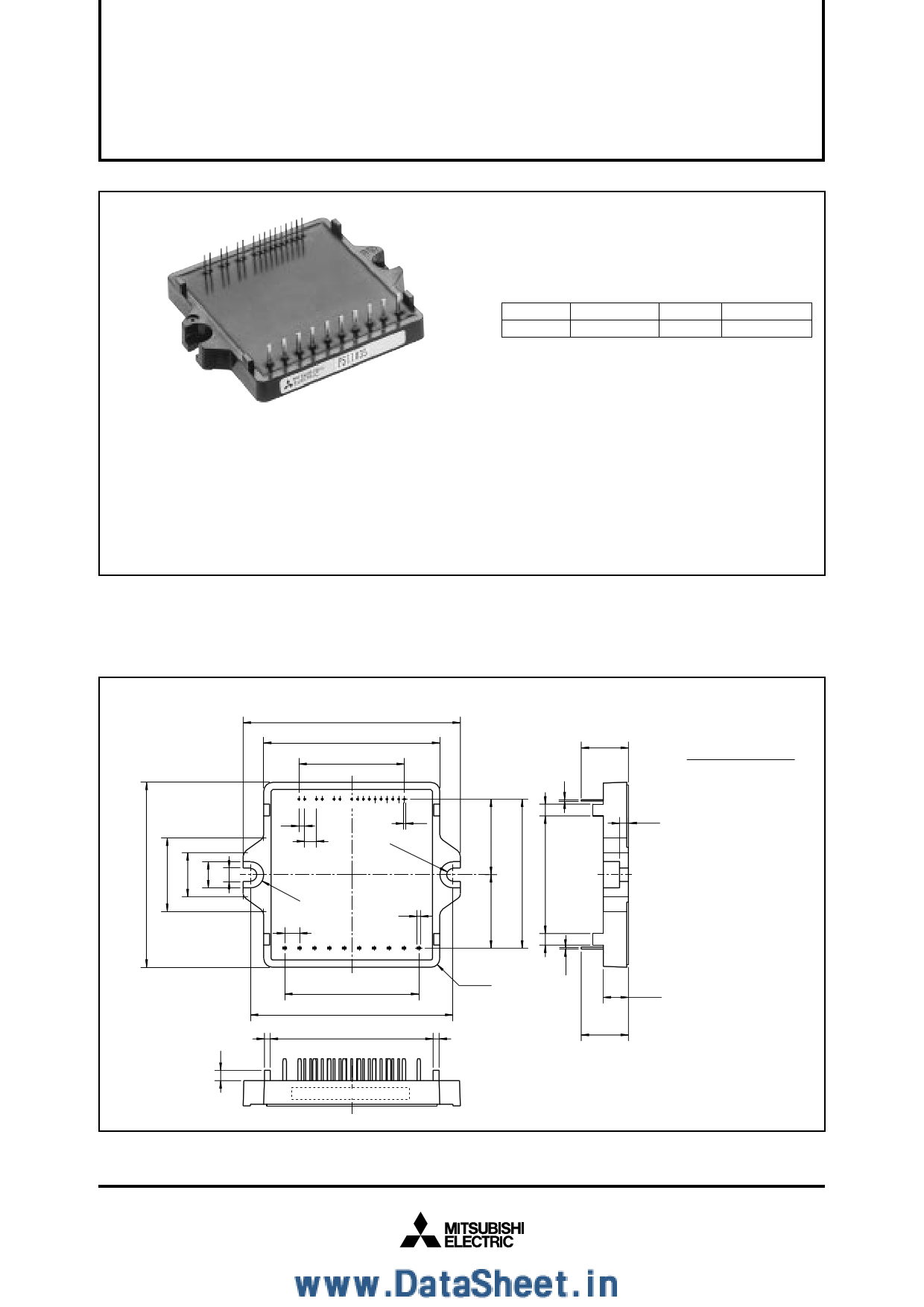
PACKAGE OUTLINES
74±1
60
36
1 2 3 4 5 6 7 8 910 12 14 16
11 13 15
2 0.6
4 2-R2.25
2-R4.5
5.08
1.2
21 22 23 24 25 26 27 28 29 30
45.72
(69)
4-R3
2 55.5 2
16.5±0.5
3±0.5
Terminals Assignment :
1. CBU+
2. CBU–
3. CBV+
4. CBV–
5. CBW+
6. CBW–
7. VD
8. UP
9. VP
10. WP
11. UN
12. VN
13. WN
14. FO
15. Vamp
16. GND
21. P1
22. R
23. S
24. T
25. N1
26. P2
27. U
28. V
29. W
30. N2
8.5±0.5
16.5±0.5
(Fig. 1)
Type name,LotNo.
Jan. 2000
1 page 
MITSUBISHI SEMICONDUCTOR <Application Specific Intelligent Power Module>
PS11035
FLAT-BASE TYPE
INSULATED TYPE
CURRENT ABNORMALITY PROTECTIVE FUNCTIONS
Ic(A)
SC
Short circuit trip level
Over current trip level
OC
Collector current
0
2
10
tw (µs)
(Fig. 5)
Protection is achieved by monitoring and filtering the N-side
DC-Bus current. The over-current protection is activated (after al-
lowing a filtering time of 10 µs) when the line current reaches
250% of the rated load-current IO (rms). Similarly, the short circuit
protection is activated (after allowing a filtering time of 2 µs) when
the line current reaches twice the rated collector-current (IC).
When a current trip-level is exceeded (OC or SC), all the N-side
IGBTs are intercepted (turned OFF) and a fault-signal is output.
After the fault-signal output duration (1.8 ms - typ.), the intercep-
tion is Reset at the following OFF input signal. However, since the
fault may be repetitive, it is recommended to stop the system after
the fault-signal is received and check the fault. The trip-level set-
tings described above are summarized in the following figure:
ARM-SHOOT-THROUGH INTER-LOCK PROTECTIVE FUNCTION
P-Side Input Signal : VCIN(p) ON
N-Side Input Signal : VCIN(n) ON
P-Side IGBT Gate : VGE(p)
0
a1
a3
a2
a4
b1
b2
b4
N-Side IGBT Gate : VGE(n) 0
(Fig. 6)
b3
Description:
(1) During the ON-State of either of the upper-arm or the lower-arm IGBT, the inter-lock protection circuit blocks any erroneous ON pulses (re-
sulting from input noise) from triggering the other arm IGBT and thus it prevents the arm-shoot-through situation.
(2) When two ON-signals are received for both the upper and the lower arms, the signal received first will be passed to the IGBT and the sec-
ond signal will be blocked. The second signal will be passed to its corresponding IGBT immediately after the first signal is OFF.
Note: This protective function provides no fault signaling output. The Dead-Time has to be set using the micro-controller (CPU).
Operation:
a1. P-side normal ON-signal ⇒ P-side IGBT gate turns ON.
a2. N-side erroneous ON-signal ⇒ N-side IGBT gate remains OFF.
a3. While P-side ON-signal remains ⇒ P-side IGBT gate remains ON.
a4. N-side normal ON-signal ⇒ N-side IGBT gate turns ON.
b1. N-side normal ON-signal ⇒ N-side IGBT gate turns ON.
b2. Simultaneous ON-signals ⇒ P-side IGBT gate remains OFF.
b3. N-side receives OFF-signal ⇒ N-side IGBT gate turns OFF.
b4. Immediately after (b3) ⇒ P-side IGBT gate turns ON.
RECOMMENDED I/O INTERFACE CIRCUIT
5V
5V
5.1kΩ
R
CPU
R
10kΩ
0.1nF 0.1nF
VD(15V) ASIPM
UP,VP,WP,UN,VN,WN
Fo
V(amp)
GND(Logic)
(Fig. 7)
Jan. 2000
5 Page | ||
| Páginas | Total 5 Páginas | |
| PDF Descargar | [ Datasheet PS11035.PDF ] | |
Hoja de datos destacado
| Número de pieza | Descripción | Fabricantes |
| PS11032 | Intellimod Module Application Specific IPM (4 Amperes/600 Volts) | Powerex Power |
| PS11033 | Intellimod Module Application Specific IPM (8 Amperes/600 Volts) | Powerex Power |
| PS11034 | Intellimod Module Application Specific IPM (15 Amperes/600 Volts) | Powerex Power |
| PS11035 | Intellimod Module Application Specific IPM (20 Amperes/600 Volts) | Powerex Power |
| Número de pieza | Descripción | Fabricantes |
| SLA6805M | High Voltage 3 phase Motor Driver IC. |
Sanken |
| SDC1742 | 12- and 14-Bit Hybrid Synchro / Resolver-to-Digital Converters. |
Analog Devices |
|
DataSheet.es es una pagina web que funciona como un repositorio de manuales o hoja de datos de muchos de los productos más populares, |
| DataSheet.es | 2020 | Privacy Policy | Contacto | Buscar |