|
|
|
PDF MCR08BT1 Data sheet ( Hoja de datos )
| Número de pieza | MCR08BT1 | |
| Descripción | SCR 0.8 AMPERE RMS 200 thru 600 Volts | |
| Fabricantes | Motorola Semiconductors | |
| Logotipo | ||
Hay una vista previa y un enlace de descarga de MCR08BT1 (archivo pdf) en la parte inferior de esta página. Total 6 Páginas | ||
|
No Preview Available !
MOTOROLA
SEMICONDUCTOR TECHNICAL DATA
Order this document
by MCR08BT1/D
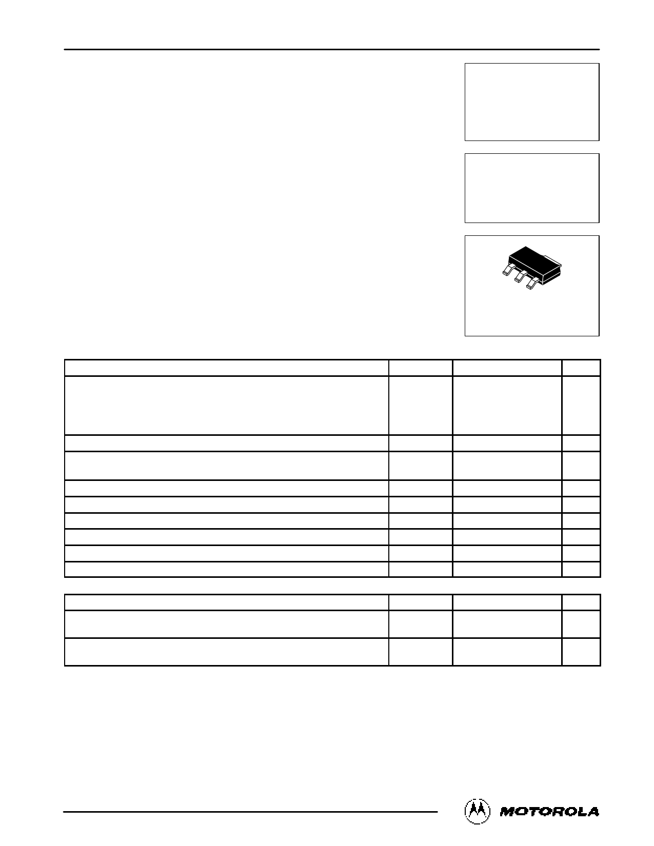
SOTĆ223 SCR
Silicon Controlled Rectifiers
Reverse Blocking Triode Thyristors
PNPN devices designed for line powered consumer applications such as relay and
lamp drivers, small motor controls, gate drivers for larger thyristors, and sensing and
detection circuits. Supplied in surface mount package for use in automated
manufacturing.
• Sensitive Gate Trigger Current
• Blocking Voltage to 600 Volts
• Glass Passivated Surface for Reliability and Uniformity
• Surface Mount Package
• Devices Supplied on 1 K Reel
MCR08BT1
Series*
*Motorola preferred devices
SCR
0.8 AMPERE RMS
200 thru 600 Volts
CASE 318E-04
(SOT-223)
STYLE 10
MAXIMUM RATINGS (TJ = 25°C unless otherwise noted)
Rating
Peak Repetitive Forward and Reverse Blocking Voltage(1)
(1/2 Sine Wave, RGK = 1000 Ω, TJ = 25 to 110°C)
MCR08BT1
MCR08DT1
MCR08MT1
Symbol
VDRM, VRRM
Value
200
400
600
Unit
Volts
On-State Current RMS (TC = 80°C)
Peak Non-repetitive Surge Current
(One Full Cycle, 60 Hz, TC = 25°C)
Circuit Fusing Considerations (t = 8.3 ms)
IT(RMS)
ITSM
I2t
0.8 Amps
10 Amps
0.4 A2s
Peak Gate Power, Forward, TA = 25°C
Average Gate Power (TC = 80°C, t = 8.3 ms)
Operating Junction Temperature Range
Storage Temperature Range
Maximum Device Temperature for Soldering Purposes (for 10 Seconds Maximum)
THERMAL CHARACTERISTICS
PGM
PG(AV)
TJ
Tstg
TL
0.1
0.01
–40 to +110
–40 to +150
260
Watts
Watts
°C
°C
°C
Characteristic
Symbol
Max Unit
Thermal Resistance, Junction to Ambient
PCB Mounted per Figure 1
RθJA
156 °C/W
Thermal Resistance, Junction to Tab
Measured on Anode Tab Adjacent to Epoxy
RθJT
25 °C/W
1. VDRM and VRRM for all types can be applied on a continuous basis. Ratings apply for zero or negative gate voltage; however, positive gate
voltage shall not be applied concurrent with negative potential on the anode. Blocking voltages shall not be tested with a constant source such
that the voltage ratings of the devices are exceeded.
Preferred devices are Motorola recommended choices for future use and best overall value.
REV 1
Motorola Thyristor Device Data
© Motorola, Inc. 1995
1
1 page 
MCR08BT1 Series
100
10
1.0
0.1
1.0
10000
TJ = 25°C
5000
1000
IGT = 48 µA
500
100
IGT = 7 µA
50
10
5.0
1.0
10 100 1000 10,000
RGK, GATE-CATHODE RESISTANCE (OHMS)
0.5
0.1
100,000 10
Vpk = 400 V
TJ = 25°
125°
110°
75°
100 1000 10,000
RGK, GATE-CATHODE RESISTANCE (OHMS)
50°
100,000
Figure 14. Holding Current Range versus
Gate-Cathode Resistance
Figure 15. Exponential Static dv/dt versus Junction
Temperature and Gate-Cathode Termination Resistance
10000
1000
500 400 V
100
300 V
200 V
100 V
TJ = 110°C
50 V
10000
1000
500
100
50
500 V
10
50
10
5.0 5.0
1.0 1.0
10 100 1000 10,000 0.01
RGK, GATE-CATHODE RESISTANCE (OHMS)
Figure 16. Exponential Static dv/dt versus Peak
Voltage and Gate-Cathode Termination Resistance
TJ = 110°C
400 V (PEAK)
RGK = 100
RGK = 1.0 k
RGK = 10 k
0.1 1.0 10
CGK, GATE-CATHODE CAPACITANCE (nF)
100
Figure 17. Exponential Static dv/dt versus
Gate-Cathode Capacitance and Resistance
10000
1000
500
100
50
10 IGT = 5 µA
5.0
IGT = 70 µA
IGT = 35 µA
1.0 IGT = 15 µA
10
100
1000
10,000
100,000
GATE-CATHODE RESISTANCE (OHMS)
Figure 18. Exponential Static dv/dt versus
Gate-Cathode Termination Resistance and
Product Trigger Current Sensitivity
Motorola Thyristor Device Data
5
5 Page | ||
| Páginas | Total 6 Páginas | |
| PDF Descargar | [ Datasheet MCR08BT1.PDF ] | |
Hoja de datos destacado
| Número de pieza | Descripción | Fabricantes |
| MCR08BT1 | SCR 0.8 AMPERE RMS 200 thru 600 Volts | Motorola Semiconductors |
| MCR08BT1 | SENSITIVE GATE SILICON CONTROLLED RECTIFIERS | ON |
| Número de pieza | Descripción | Fabricantes |
| SLA6805M | High Voltage 3 phase Motor Driver IC. |
Sanken |
| SDC1742 | 12- and 14-Bit Hybrid Synchro / Resolver-to-Digital Converters. |
Analog Devices |
|
DataSheet.es es una pagina web que funciona como un repositorio de manuales o hoja de datos de muchos de los productos más populares, |
| DataSheet.es | 2020 | Privacy Policy | Contacto | Buscar |