|
|
|
PDF LB-9 Data sheet ( Hoja de datos )
| Número de pieza | LB-9 | |
| Descripción | Universal Balancing Techniques | |
| Fabricantes | National | |
| Logotipo | ||
Hay una vista previa y un enlace de descarga de LB-9 (archivo pdf) en la parte inferior de esta página. Total 3 Páginas | ||
|
No Preview Available !
Universal Balancing
Techniques
National Semiconductor
Linear Brief 9
August 1969
IC op amps are widely accepted as a universal analog
component. Although the circuit designs may vary, most
devices are functionally interchangeable. However, offset
voltage balancing remains a personality trait of the particular
amplifier design. The techniques shown here allow offset
voltage balancing without regard to the internal circuitry of
the amplifier.
00846002
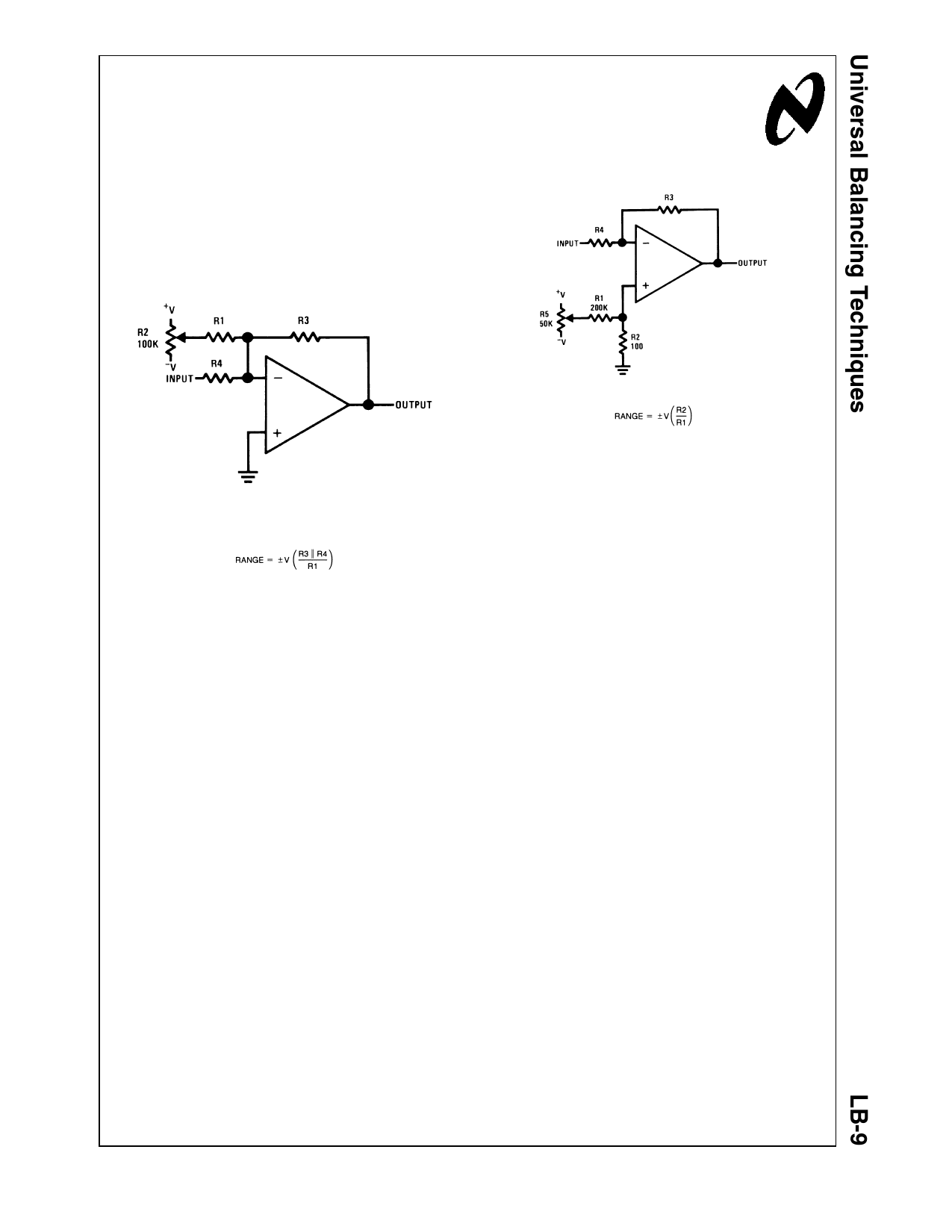
R1 = 2000 R3 \ R4
R4 \ R3 ≤ 10 kΩ
00846001
FIGURE 1. Offset Voltage Adjustment for Inverting
Amplifiers Using 10 kΩ Source Resistance or Less
The circuit shown in Figure 1 is used to balance out the
offset voltage of inverting amplifiers having a source resis-
tance of 10 kΩ or less. A small current is injected into the
summing node of the amplifier through R1. Since R1 is 2000
times as large as the source resistance the voltage at the
arm of the pot is attenuated by a factor of 2000 at the
summing node. With the values given and ±15V supplies the
output may be zeroed for offset voltages up to ±7.5 mW.
If the value of the source resistance is much larger than 10
kΩ, the resistance needed for R1 becomes too large. In this
case it is much easier to balance out the offset by supplying
a small voltage at the non-inverting input of the amplifier.
Figure 2 shows such a scheme. Resistors R1 and R2 divide
the voltage at the arm of the pot to supply a ±7.5 mW
adjustment range with ±15V supplies.
This adjustment method is also useful when the feedback
element is a capacitor or non-linear device.
FIGURE 2. Offset Voltage Adjustment for Inverting
Amplifiers Using Any Type of Feedback Element
This technique of supplying a small voltage effectively in
series with the input is also used for adjusting non-inverting
amplifiers. As is shown in Figure 3, divider R1, R2 reduces
the voltage at the arm of the pot to ±7.5 mW for offset
adjustment. Since R2 appears in series with R4, R2 should
be considered when calculating the gain. If R4 is greater than
10 kΩ the error due to R2 is less than 1%.
© 2002 National Semiconductor Corporation AN008460
www.national.com
1 page | ||
| Páginas | Total 3 Páginas | |
| PDF Descargar | [ Datasheet LB-9.PDF ] | |
Hoja de datos destacado
| Número de pieza | Descripción | Fabricantes |
| LB-202BL | High efficiency / two-digit numeric displays | ROHM Semiconductor |
| LB-203BL | High efficiency / three-digit numeric displays | ROHM Semiconductor |
| LB-302FP | High efficiency / two-digit numeric displays | ROHM Semiconductor |
| LB-303AK | High efficiency / three-digit numeric displays | ROHM Semiconductor |
| Número de pieza | Descripción | Fabricantes |
| SLA6805M | High Voltage 3 phase Motor Driver IC. |
Sanken |
| SDC1742 | 12- and 14-Bit Hybrid Synchro / Resolver-to-Digital Converters. |
Analog Devices |
|
DataSheet.es es una pagina web que funciona como un repositorio de manuales o hoja de datos de muchos de los productos más populares, |
| DataSheet.es | 2020 | Privacy Policy | Contacto | Buscar |