|
|
|
PDF X9116 Data sheet ( Hoja de datos )
| Número de pieza | X9116 | |
| Descripción | Digitally Controlled Potentiometer (XDCP) | |
| Fabricantes | Xicor | |
| Logotipo | ||
Hay una vista previa y un enlace de descarga de X9116 (archivo pdf) en la parte inferior de esta página. Total 11 Páginas | ||
|
No Preview Available !
APPLICATION NOTE
AVAILABLE
AN99 • AN115 • AN120 • AN124 • AN133 • AN134
Low Noise, Low Power, Low Cost
X9116
Digitally Controlled Potentiometer (XDCP™)
FEATURES
• Solid-state nonvolatile
• 16 wiper taps
• 3-wire up/down serial interface
• VCC = 2.7V and 5V
• Active current < 50µA max.
• Standby current < 1µA max.
• RTOTAL = 10KΩ
• Packages: MSOP-8, SOIC
DESCRIPTION
The Xicor X9116 is a digitally controlled nonvolatile
potentiometer designed to be used in trimmer applica-
tions. The pot consists of 15 equal resistor segments
that connect to the wiper pin through programmable
CMOS switches. The tap position is programmed
through a 3-wire up/down serial port. The last position
of the wiper is stored in a nonvolatile memory location
which is recalled at the time of power up of the device.
The wiper moves through sequential tap positions with
inputs on the serial port. A falling edge on INC (bar)
causes the tap position to increment one position up or
down based on whether the U/D (bar) pin is held high
or low.
The X9116 can be used in many applications requiring
a variable resistance. In many cases it can replace a
mechanical trimmer and offers many advantages such
as temperature and time stability as well as the reli-
ability of a solid state solution.
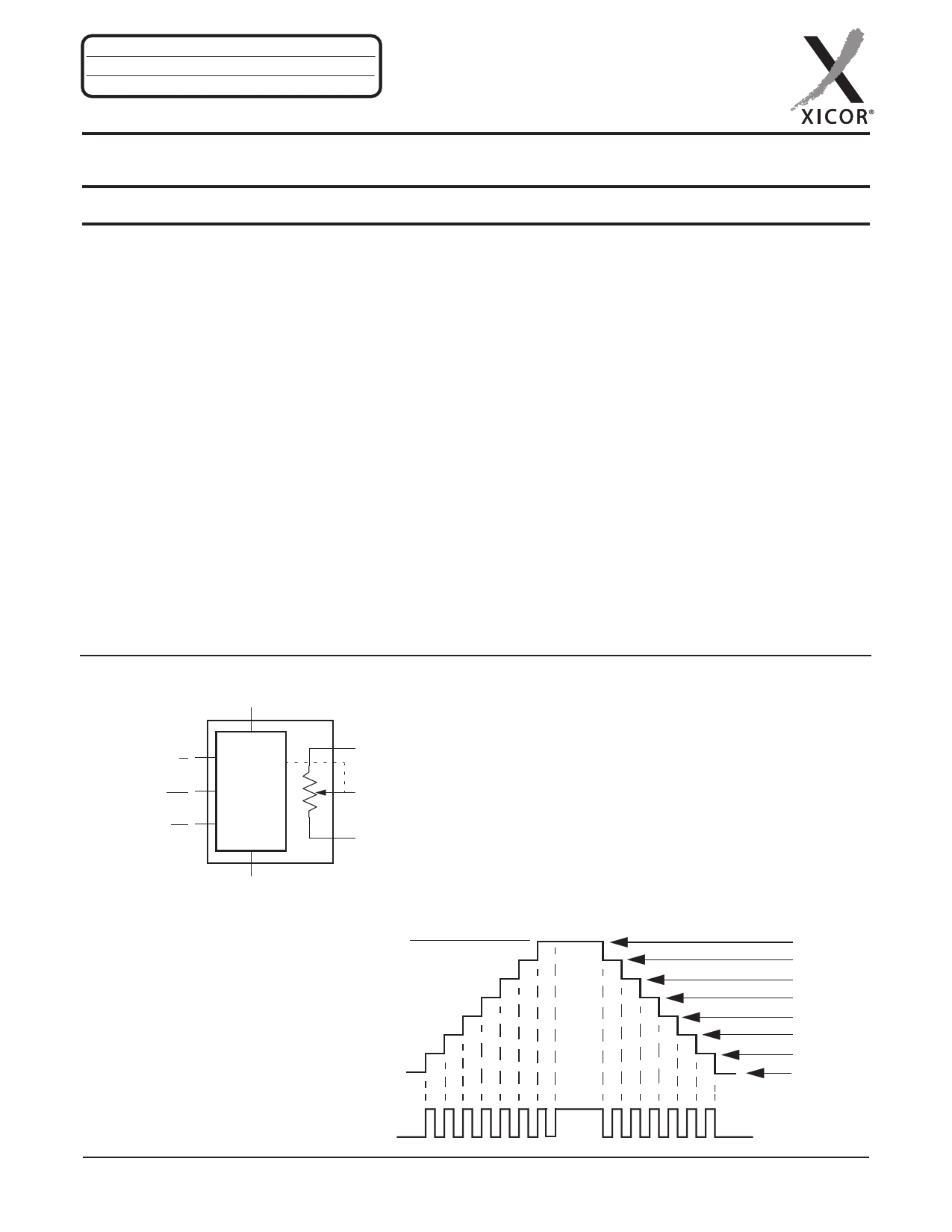
BLOCK DIAGRAM
VCC (Supply Voltage)
Up/Down
(U/D)
Increment
(INC)
Device Select
(CS)
Control
and
Memory
VSS (Ground)
General
RH/VH
RW/VW
RL/VL
RW-RL Resistance
RH
15
14
13
*
3
2
1
RL 0
10kΩ
9.34kΩ
8.68kΩ
* kΩ
2.08kΩ
1.42kΩ
760Ω
100Ω
REV 1.2 2/5/03
www.xicor.com
Characteristics subject to change without notice. 1 of 11
1 page 
X9116
D.C. OPERATING CHARACTERISTICS (Over recommended operating conditions unless otherwise specified)
Symbol
Parameter
ICC1 VCC active current (Increment)
Min.
Limits
Typ.(4)
Max.
150
ICC2
ISB
VCC active current (Store)
(EEPROM Store)
Standby supply current
400
1
ILI
VIH
VIL
CIN(5)
CS, INC, U/D input leakage
current
CS, INC, U/D input HIGH voltage
CS, INC, U/D input LOW voltage
CS, INC, U/D input capacitance
2V
–0.5
±10
VCC + 0.5
0.8
10
Notes: (4) Typical values are for TA = 25°C and nominal supply voltage.
(5) This parameter is periodically sampled and not 100% tested.
Unit
µA
µA
µA
µA
V
V
pF
Test Conditions
CS = VIL, U/D = VIL or VIH and
INC = 0.4V/2.4V @ max. tCYC
CS = VIH, U/D = VIL or VIH and
INC = VIH @ max. tWR
CS = VCC–0.3V, U/D and
INC = VSS or VCC–0.3V
VIN = VSS to VCC
VCC = 5V, VIN = VSS,
TA = 25°C, f = 1MHz
ENDURANCE AND DATA RETENTION
Parameter
Minimum endurance
Data retention
Min.
100,000
100
Unit
Data changes per bit
Years
Test Circuit #1
VH/RH
Test Circuit #2
VH/RH
VS Test Point
Test Point
VW/RW
VWV/RWW
Force
VL/RL
VLL/RL
Current
A.C. CONDITIONS OF TEST
Input pulse levels
Input rise and fall times
Input reference levels
0V to 3V
10ns
1.5V
Circuit #3 SPICE Macro Model
RTOTAL
RH RL
CH
CW CL
10pF
10pF
25pF
RW
REV 1.2 2/5/03
www.xicor.com
Characteristics subject to change without notice. 5 of 11
5 Page 
X9116
Ordering Information
X9116X
XXX
VCC Limits
Blank = 5V ±10%
–2.7 = 2.7V to 5.5V
Temperature Range
Blank = Commercial = 0°C to +70°C
I = Industrial = –40°C to +85°C
Package
M8 = 8-Lead MSOP
S8 = 8-Lead SOIC
End to End Resistance
W = 10KΩ
LIMITED WARRANTY
©Xicor, Inc. 2000 Patents Pending
Devices sold by Xicor, Inc. are covered by the warranty and patent indemnification provisions appearing in its Terms of Sale only. Xicor, Inc. makes no warranty,
express, statutory, implied, or by description regarding the information set forth herein or regarding the freedom of the described devices from patent infringement.
Xicor, Inc. makes no warranty of merchantability or fitness for any purpose. Xicor, Inc. reserves the right to discontinue production and change specifications and prices
at any time and without notice.
Xicor, Inc. assumes no responsibility for the use of any circuitry other than circuitry embodied in a Xicor, Inc. product. No other circuits, patents, or licenses are implied.
TRADEMARK DISCLAIMER:
Xicor and the Xicor logo are registered trademarks of Xicor, Inc. AutoStore, Direct Write, Block Lock, SerialFlash, MPS, and XDCP are also trademarks of Xicor, Inc. All
others belong to their respective owners.
U.S. PATENTS
Xicor products are covered by one or more of the following U.S. Patents: 4,326,134; 4,393,481; 4,404,475; 4,450,402; 4,486,769; 4,488,060; 4,520,461; 4,533,846;
4,599,706; 4,617,652; 4,668,932; 4,752,912; 4,829,482; 4,874,967; 4,883,976; 4,980,859; 5,012,132; 5,003,197; 5,023,694; 5,084,667; 5,153,880; 5,153,691;
5,161,137; 5,219,774; 5,270,927; 5,324,676; 5,434,396; 5,544,103; 5,587,573; 5,835,409; 5,977,585. Foreign patents and additional patents pending.
LIFE RELATED POLICY
In situations where semiconductor component failure may endanger life, system designers using this product should design the system with appropriate error detection
and correction, redundancy and back-up features to prevent such an occurrence.
Xicor’s products are not authorized for use in critical components in life support devices or systems.
1. Life support devices or systems are devices or systems which, (a) are intended for surgical implant into the body, or (b) support or sustain life, and whose failure to
perform, when properly used in accordance with instructions for use provided in the labeling, can be reasonably expected to result in a significant injury to the user.
2. A critical component is any component of a life support device or system whose failure to perform can be reasonably expected to cause the failure of the life
support device or system, or to affect its safety or effectiveness.
REV 1.2 2/5/03
www.xicor.com
Characteristics subject to change without notice. 11 of 11
11 Page | ||
| Páginas | Total 11 Páginas | |
| PDF Descargar | [ Datasheet X9116.PDF ] | |
Hoja de datos destacado
| Número de pieza | Descripción | Fabricantes |
| X9110 | Single Digitally-Controlled (XDCP) Potentiometer | Xicor |
| X9110 | Single Digitally Controlled Potentiometer | Intersil |
| X9111 | Single Digitally-Controlled Potentiometer | Xicor |
| X9111 | Single Digitally Controlled Potentiometer | Intersil |
| Número de pieza | Descripción | Fabricantes |
| SLA6805M | High Voltage 3 phase Motor Driver IC. |
Sanken |
| SDC1742 | 12- and 14-Bit Hybrid Synchro / Resolver-to-Digital Converters. |
Analog Devices |
|
DataSheet.es es una pagina web que funciona como un repositorio de manuales o hoja de datos de muchos de los productos más populares, |
| DataSheet.es | 2020 | Privacy Policy | Contacto | Buscar |