|
|
|
PDF AD5235 Data sheet ( Hoja de datos )
| Número de pieza | AD5235 | |
| Descripción | Dual 1024-Position Digital Potentiometer | |
| Fabricantes | Analog Devices | |
| Logotipo | ||
Hay una vista previa y un enlace de descarga de AD5235 (archivo pdf) en la parte inferior de esta página. Total 30 Páginas | ||
|
No Preview Available !
Data Sheet
Nonvolatile Memory, Dual
1024-Position Digital Potentiometer
AD5235
FEATURES
Dual-channel, 1024-position resolution
25 kΩ, 250 kΩ nominal resistance
Maximum ±8% nominal resistor tolerance error
Low temperature coefficient: 35 ppm/°C
2.7 V to 5 V single supply or ±2.5 V dual supply
SPI-compatible serial interface
Nonvolatile memory stores wiper settings
Power-on refreshed with EEMEM settings
Permanent memory write protection
Resistance tolerance stored in EEMEM
26 bytes extra nonvolatile memory for user-defined
information
1M programming cycles
100-year typical data retention
APPLICATIONS
DWDM laser diode driver, optical supervisory systems
Mechanical potentiometer replacement
Instrumentation: gain, offset adjustment
Programmable voltage-to-current conversion
Programmable filters, delays, time constants
Programmable power supply
Low resolution DAC replacement
Sensor calibration
GENERAL DESCRIPTION
The AD5235 is a dual-channel, nonvolatile memory,1 digitally
controlled potentiometer2 with 1024-step resolution, offering
guaranteed maximum low resistor tolerance error of ±8%.
The device performs the same electronic adjustment function
as a mechanical potentiometer with enhanced resolution, solid
state reliability, and superior low temperature coefficient per-
formance. The versatile programming of the AD5235 via an
SPI®-compatible serial interface allows 16 modes of operation
and adjustment including scratchpad programming, memory
storing and restoring, increment/decrement, ±6 dB/step log taper
adjustment, wiper setting readback, and extra EEMEM1 for user-
defined information such as memory data for other components,
look-up table, or system identification information.
1 The terms nonvolatile memory and EEMEM are used interchangeably.
2 The terms digital potentiometer and RDAC are used interchangeably.
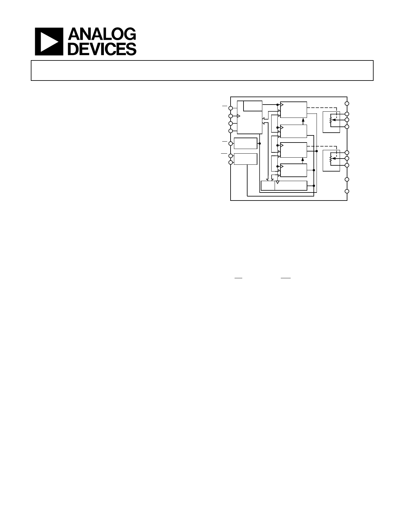
FUNCTIONAL BLOCK DIAGRAM
CS
CLK
SDI
SDO
ADDR
DECODE
SERIAL
INTERFACE
PR
POWER-ON
RESET
WP
RDY
EEMEM
CONTROL
RDAC1
REGISTER
AD5235
EEMEM1
RDAC2
REGISTER
EEMEM2
RDAC1
RDAC2
RTOL*
26 BYTES
USER EEMEM
VDD
A1
W1
B1
A2
W2
B2
VSS
GND
*RAB TOLERANCE
Figure 1.
In the scratchpad programming mode, a specific setting can
be programmed directly to the RDAC2 register, which sets the
resistance between Terminal W and Terminal A and Terminal W
and Terminal B. This setting can be stored into the EEMEM
and is restored automatically to the RDAC register during
system power-on.
The EEMEM content can be restored dynamically or through
external PR strobing, and a WP function protects EEMEM
contents. To simplify the programming, the independent or
simultaneous linear-step increment or decrement commands
can be used to move the RDAC wiper up or down, one step at
a time. For logarithmic ±6 dB changes in the wiper setting, the
left or right bit shift command can be used to double or halve the
RDAC wiper setting.
The AD5235 patterned resistance tolerance is stored in the
EEMEM. The actual end-to-end resistance can, therefore, be
known by the host processor in readback mode. The host can
execute the appropriate resistance step through a software
routine that simplifies open-loop applications as well as
precision calibration and tolerance matching applications.
The AD5235 is available in a thin, 16-lead TSSOP package.
The part is guaranteed to operate over the extended industrial
temperature range of −40°C to +85°C.
Rev. F
Information furnished by Analog Devices is believed to be accurate and reliable. However, no
responsibilityisassumedbyAnalogDevices for itsuse,nor foranyinfringementsofpatentsor other
rights of third parties that may result from its use. Specifications subject to change without notice. No
license is granted by implication or otherwise under any patent or patent rights of Analog Devices.
Trademarksandregisteredtrademarksarethepropertyoftheirrespectiveowners.
One Technology Way, P.O. Box 9106, Norwood, MA 02062-9106, U.S.A.
Tel: 781.329.4700
www.analog.com
Fax: 781.461.3113 ©2004–2012 Analog Devices, Inc. All rights reserved.
1 page 
Data Sheet
AD5235
Parameter
POWER SUPPLIES
Single-Supply Power Range
Dual-Supply Power Range
Positive Supply Current
Negative Supply Current
EEMEM Store Mode Current
EEMEM Restore Mode Current7
Power Dissipation8
Power Supply Sensitivity5
DYNAMIC CHARACTERISTICS5, 9
Bandwidth
Total Harmonic Distortion
Symbol
VDD
VDD/VSS
IDD
ISS
IDD (store)
ISS (store)
IDD (restore)
ISS (restore)
PDISS
PSS
BW
THDW
VW Settling Time
tS
Resistor Noise Density
Crosstalk (CW1/CW2)
Analog Crosstalk
eN_WB
CT
CTA
Conditions
Min Typ1
Max Unit
VSS = 0 V
VIH = VDD or VIL = GND
VDD = +2.5 V, VSS = −2.5 V
VIH = VDD or VIL = GND
VIH = VDD or VIL = GND,
VSS = GND, ISS ≈ 0
VDD = +2.5 V, VSS = −2.5 V
VIH = VDD or VIL = GND,
VSS = GND, ISS ≈ 0
VDD = +2.5 V, VSS = −2.5 V
VIH = VDD or VIL = GND
∆VDD = 5 V ± 10%
2.7
±2.25
2
−4 −2
2
−2
320
−320
10
0.006
5.5
±2.75
5
V
V
µA
µA
mA
mA
µA
µA
30 µW
0.01 %/%
−3 dB, RAB = 25 kΩ/250 kΩ
VA = 1 V rms, VB = 0 V,
f = 1 kHz, code = midscale
RAB = 25 kΩ
RAB = 250 kΩ
VA = VDD, VB = 0 V, VW = 0.50% error
band, from zero scale to midscale
RAB = 25 kΩ
RAB = 250 kΩ
RAB = 25 kΩ/250 kΩ
VA1 = VDD, VB1 = VSS , measured VW2
with VW1 making full-scale change,
RAB = 25 kΩ/250 kΩ
VAB2 = 5 V p-p, f = 1 kHz, measured
VW1, Code 1 = midscale, Code 2 =
full scale, RAB = 25 kΩ/250 kΩ
125/12
0.009
0.035
4
36
20/64
30/60
−110/−100
kHz
%
%
µs
µs
nV/√Hz
nV-s
dB
1 Typicals represent average readings at 25°C and VDD = 5 V.
2 Resistor position nonlinearity error (R-INL) is the deviation from an ideal value measured between the maximum resistance and the minimum resistance wiper
positions. R-DNL measures the relative step change from ideal between successive tap positions. IWB = (VDD − 1)/RWB (see Figure 27).
3 INL and DNL are measured at VW with the RDAC configured as a potentiometer divider similar to a voltage output DAC. VA = VDD and VB = VSS. DNL specification limits of
±1 LSB maximum are guaranteed monotonic operating conditions (see Figure 28).
4 Resistor Terminal A, Resistor Terminal B, and Resistor Terminal W have no limitations on polarity with respect to each other. Dual-supply operation enables ground-
referenced bipolar signal adjustment.
5 Guaranteed by design and not subject to production test.
6 Common-mode leakage current is a measure of the dc leakage from any Terminal A, Terminal B, or Terminal W to a common-mode bias level of VDD/2.
7 EEMEM restore mode current is not continuous. Current is consumed while EEMEM locations are read and transferred to the RDAC register.
8 PDISS is calculated from (IDD × VDD) + (ISS × VSS).
9 All dynamic characteristics use VDD = +2.5 V and VSS = −2.5 V.
Rev. F | Page 5 of 32
5 Page 
Data Sheet
60
2.7V
3.0V
3.3V
50 5.0V
5.5V
40
30
20
10
0
0 200 400 600 800
CODE (Decimal)
Figure 11. Wiper On Resistance vs. Code
1000
3
IDD = 2.7V
IDD = 3.3V
IDD = 3.0V
2 IDD = 5.0V
IDD = 5.5V
1
0
–1
–2
–3
–40
ISS = 2.7V
ISS = 3.3V
ISS = 3.0V
ISS = 5.0V
ISS = 5.5V
–20 0
20 40 60
TEMPERATURE (°C)
Figure 12. IDD vs. Temperature
80 85
50
FULL SCALE
MIDSCALE
ZERO SCALE
40
30
20
10
0
123456789
FREQUENCY (MHz)
Figure 13. IDD vs. Clock Frequency, RAB = 25 kΩ
10
AD5235
2.7V
3.0V
400 3.3V
5.0V
5.5V
300
200
100
0
012345
VDIO (V)
Figure 14. IDD vs. Digital Input Voltage
0.12
0.10
0.08
0.06
0.04
0.02
0
10
250kΩ
25kΩ
100 1k 10k
FREQUENCY (Hz)
Figure 15. THD + Noise vs. Frequency
100k
10
1
0.1
250kΩ
0.01 25kΩ
0.001
0.0001
0.001
0.01
0.1
1
AMPLITUDE (V rms)
Figure 16. THD + Noise vs. Amplitude
10
Rev. F | Page 11 of 32
11 Page | ||
| Páginas | Total 30 Páginas | |
| PDF Descargar | [ Datasheet AD5235.PDF ] | |
Hoja de datos destacado
| Número de pieza | Descripción | Fabricantes |
| AD5231 | 1024-Position Digital Potentiometer | Analog Devices |
| AD5232 | Dual 256-Position Digital Potentiometer | Analog Devices |
| AD5233 | Quad 64-Position Digital Potentiometer | Analog Devices |
| AD5235 | Dual 1024-Position Digital Potentiometer | Analog Devices |
| Número de pieza | Descripción | Fabricantes |
| SLA6805M | High Voltage 3 phase Motor Driver IC. |
Sanken |
| SDC1742 | 12- and 14-Bit Hybrid Synchro / Resolver-to-Digital Converters. |
Analog Devices |
|
DataSheet.es es una pagina web que funciona como un repositorio de manuales o hoja de datos de muchos de los productos más populares, |
| DataSheet.es | 2020 | Privacy Policy | Contacto | Buscar |