|
|
|
PDF IAB110P Data sheet ( Hoja de datos )
| Número de pieza | IAB110P | |
| Descripción | Integrated Telecom Circuits | |
| Fabricantes | IXYS | |
| Logotipo | ||
Hay una vista previa y un enlace de descarga de IAB110P (archivo pdf) en la parte inferior de esta página. Total 8 Páginas | ||
|
No Preview Available !
INTEGRATED CIRCUITS DIVISION
IAB110P
Integrated Telecom Circuits
Parameter
Blocking Voltage
Load Current
On-Resistance (max)
Rating
350
100
35
Units
VP
mArms / mADC
Features
• 3750Vrms Input/Output Isolation
• Three Functions in One Package
• Bidirectional Current Sensing
• Bidirectional Current Switching
• FCC Compatible
• No EMI/RFI Generation
• Small 16-Pin SOIC Package (PCMCIA Compatible)
• Machine Insertable, Wave Solderable
• Tape & Reel Versions Available
Applications
• Telecommunications
• Telecom Switching
• Tip/Ring Circuits
• Modem Switching (Laptop, Notebook, Pocket Size)
• Hook Switch
• Dial Pulsing
• Ground Start
• Ringer Injection
• Instrumentation
• Multiplexers
• Data Acquisition
• Electronic Switching
• I/O Subsystems
• Meters (Watt-Hour, Water, Gas)
• Medical Equipment-Patient/Equipment Isolation
• Security
• Aerospace
• Industrial Controls
Description
The IAB110P Multifunction Telecom switch combines
one 350V single-pole, normally open (1-Form-A)
relay; one 350V single-pole, normally closed
(1-Form-B) relay; and one bidirectional optocoupler in
a single package. Optically coupled relay outputs that
use the patented OptoMOS architecture are
controlled by a highly efficient GaAIAs infrared LED.
The IAB110P allows telecom circuit designers to
combine three discrete functions in a single
component, whose small package uses less space
than traditional discrete component solutions.
Approvals
• UL Recognized Component: File E76270
• CSA Certified Component: Certificate 1305490
• EN/IEC 60950-1 Certified Component:
TUV Certificate: B 09 07 49410 006
Ordering Information
Part #
IAB110P
IAB110PTR
Description
16-Pin SOIC (50/Tube)
16-Pin SOIC (1000/Reel)
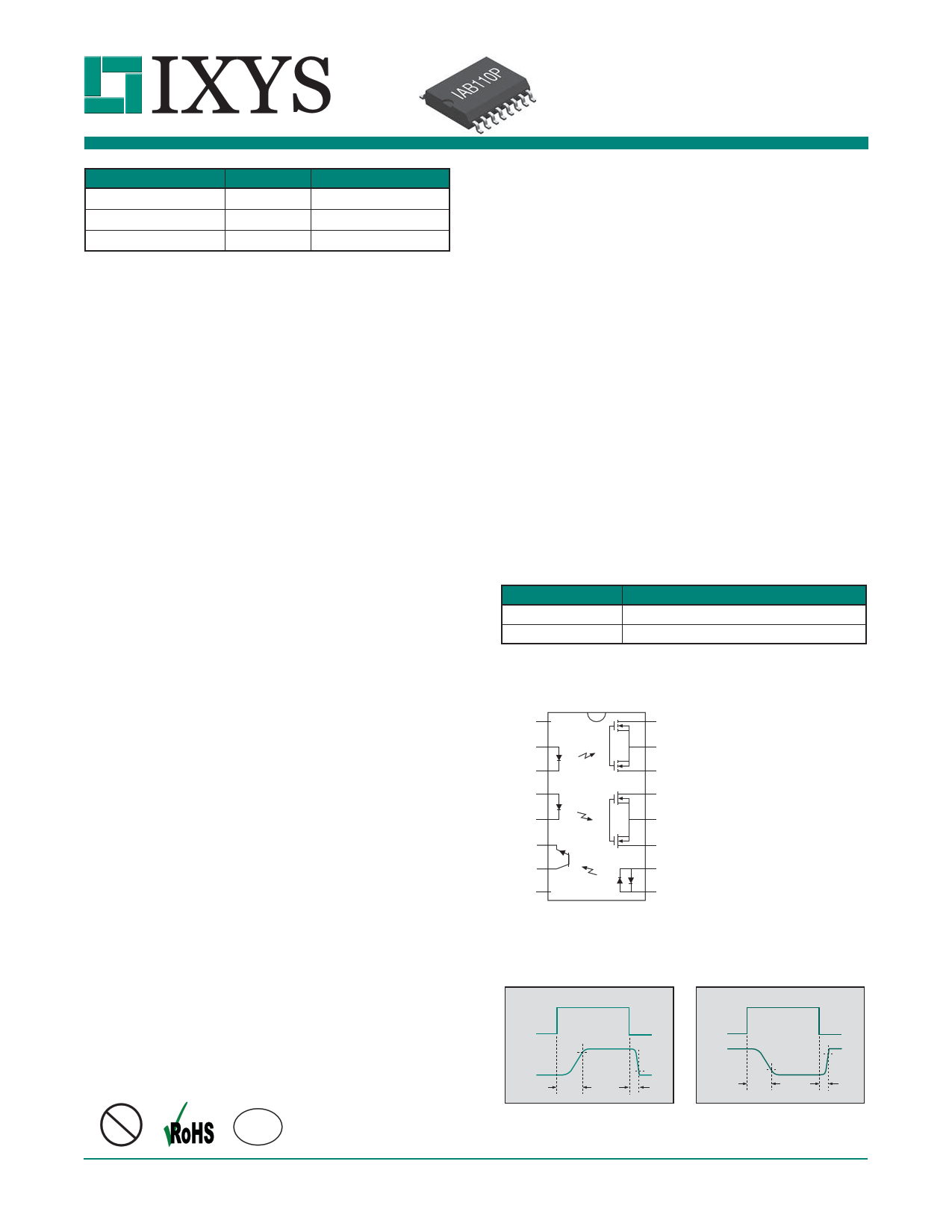
Pin Configuration
1
(N/C)
2
3
4
5
6
7
8
(N/C)
16
15 (Form A)
14
13
12 (Form B)
11
10
9
1. (N/C)
2. + LED - Form A Relay #1
3. – LED - Form A Relay #1
4. + LED - Form B Relay #2
5. – LED - Form B Relay #2
6. Emitter - Phototransistor
7. Collector - Phototransistor
8. (N/C)
9. LED - Phototransistor +/–
10. LED - Phototransistor –/+
11. Output - Form B Relay #2
12. Common Source Relay #2
13. Output - Form B Relay #2
14. Output - Form A Relay #1
15. Common Source Relay #1
16. Output - Form A Relay #1
Pb
DS-IAB110P-R04
e3
Switching Characteristics of
Normally Open Devices
Form-A
IF
ILOAD
90%
ton
10%
toff
Switching Characteristics of
Normally Closed Devices
Form-B
IF
ILOAD
10%
toff
90%
ton
www.ixysic.com
1
1 page 
INTEGRATED CIRCUITS DIVISION
IAB110P
1-FORM-B RELAY PERFORMANCE DATA*
1-Form-B
Typical Turn-On Time
(N=50, IF=5mA, IL=100mADC, TA=25ºC)
25
1-Form-B
Typical Turn-Off Time
(N=50, I =5mA, I =100mA , T =25ºC)
FL
DC A
25
1-Form-B
Typical On-Resistance Distribution
(N=50, IF=5mA, IL=100mADC, TA=25ºC)
25
20 20 20
15 15 15
10 10 10
555
0
0.09 0.27 0.45 0.63 0.81 0.99 1.17
Turn-On Time (ms)
0
0.27 0.45 0.63 0.81 0.99 1.17 1.35
Turn-Off Time (ms)
0
25.5 26.5 27.5 28.5 29.5 30.5 31.5
On-Resistance (:)
1-Form-B
Typical IF for Switch Operation
(N=50, IL=100mADC, TA=25ºC)
25
20
15
10
5
0
0.33 0.55 0.77 0.99 1.21 1.43 1.65
LED Current (mA)
1-Form-B
Turn-On Time vs. LED Forward Current
(IL=100mADC)
0.30
0.25
0.20
0.15
0.10
0.05
0
0 5 10 15 20 25 30 35 40 45 50
LED Forward Current (mA)
1-Form-B
Turn-Off Time vs. LED Forward Current
(IL=100mADC)
0.7
0.6
0.5
0.4
0.3
0.2
0.1
0
0 5 10 15 20 25 30 35 40 45 50
LED Forward Current (mA)
1-Form-B
Typical IF for Switch Dropout
(N=50, IL=100mADC, TA=25ºC)
25
20
15
10
5
0
0.11 0.33 0.55 0.77 0.99 1.21 1.43
LED Current (mA)
1-Form-B
Typical Turn-On Time vs. Temperature
(IF=5mA, IL=100mADC)
0.6
0.5
0.4
0.3
0.2
0.1
0
-40 -20
0 20 40 60
Temperature (ºC)
80 100
1-Form-B
Typical Turn-Off Time vs. Temperature
(IL=100mADC)
0.9
0.8
0.7
0.6 IF=5mA
0.5
IF=10mA
IF=20mA
0.4
0.3
0.2
0.1
0
-40 -20
0
20 40 60
80 100
Temperature (ºC)
1-Form-B
Typical Blocking Voltage Distribution
(N=50, TA=25ºC)
25
20
15
10
5
0
357.5 372.5 387.5 402.5 417.5 432.5 443.5
Blocking Voltage (VP)
1-Form-B
Typical IF for Switch Operation
vs. Temperature
(IL=100mADC)
3.0
2.5
2.0
1.5
1.0
0.5
0
-40
3.0
-20 0 20 40 60 80
Temperature (ºC)
1-Form-B
Typical IF for Switch Dropout
vs. Temperature
(IL=100mADC)
100
2.5
2.0
1.5
1.0
0.5
0
-40 -20
0 20 40 60
Temperature (ºC)
80 100
* The Performance data shown in the graphs above is typical of device performance. For guaranteed parameters not indicated in the written specifications, please contact our application
department.
R04 www.ixysic.com
5
5 Page | ||
| Páginas | Total 8 Páginas | |
| PDF Descargar | [ Datasheet IAB110P.PDF ] | |
Hoja de datos destacado
| Número de pieza | Descripción | Fabricantes |
| IAB110P | Integrated Telecom Circuits | Clare |
| IAB110P | Integrated Telecom Circuits | IXYS |
| Número de pieza | Descripción | Fabricantes |
| SLA6805M | High Voltage 3 phase Motor Driver IC. |
Sanken |
| SDC1742 | 12- and 14-Bit Hybrid Synchro / Resolver-to-Digital Converters. |
Analog Devices |
|
DataSheet.es es una pagina web que funciona como un repositorio de manuales o hoja de datos de muchos de los productos más populares, |
| DataSheet.es | 2020 | Privacy Policy | Contacto | Buscar |