|
|
|
PDF 844S42I Data sheet ( Hoja de datos )
| Número de pieza | 844S42I | |
| Descripción | Dual Output RF Frequency Synthesizer | |
| Fabricantes | IDT | |
| Logotipo | ||
Hay una vista previa y un enlace de descarga de 844S42I (archivo pdf) en la parte inferior de esta página. Total 28 Páginas | ||
|
No Preview Available !
Dual Output RF Frequency Synthesizer
844S42I
Data Sheet
General Description
The 844S42I is a 3.3V compatible, PLL based clock synthesizer
targeted for clock generation in high-performance instrumentation,
networking and computing applications. Using either the serial (I2C)
or parallel programming interface, the 844S42I enables the
generation of clock frequencies in the range of 81MHz to 2592MHz.
The internal crystal oscillator uses the external quartz crystal as the
basis of its frequency reference. Alternatively, a LVCMOS compatible
clock signal can be used as PLL reference signal. The devices uses
an integer-N synthesizer architecture and is optimized for low-jitter
generation. The VCO within the PLL operates over a range of
1296MHz to 2592MHz. Its output is scaled by a divider that is
configured by either the I2C or parallel interfaces. The crystal
oscillator frequency fXTAL, the PLL pre-divider P, the feedback-divider
M and the PLL post-divider N determine the output frequency. The
feedback path of the PLL is internal.
The PLL post-dividers NA and NB are configured through either the
I2C or the parallel interfaces, each can provide one of seven division
ratios (1, 2, 3, 4, 6, 8, 16). This divider extends the performance of
the part while providing a typical 50% duty cycle. The high-frequency
outputs QA and QB are differential and are capable of driving a pair
of transmission lines. The positive supply voltage for the internal PLL
is separated from the power supply for the core logic and output
drivers to minimize noise induced jitter. The serial interface is I2C
compatible and provides read and write access to the internal PLL
configuration registers. The lock state of the PLL is indicated by the
LVCMOS-compatible LOCK_DT output. The 844S42I is packaged
in a 8mm x 8mm 56-lead VFQFN package.
Features
• Programmable frequency synthesis optimized for instrumentation,
networking and computing applications
• 81MHz to 2592MHz synthesized clock output signal
• Two differential, universal LVDS or LVPECL compatible
high-frequency outputs
• Output frequency programmable through 2-wire I2C bus or
parallel interface
• On-chip crystal oscillator for reference frequency generation
• Alternative LVCMOS/LVTTL compatible reference clock input
• Clock stop and output enable functionality
• PLL lock indicator output (LVCMOS/LVTTL)
• LVCMOS/LVTTL compatible control inputs
• Fully integrated PLL
• SiGe Technology
• Full 3.3V supply voltage
• -40°C to 85°C ambient operating temperature
• Available in a lead-free (RoHS 6) compliant package
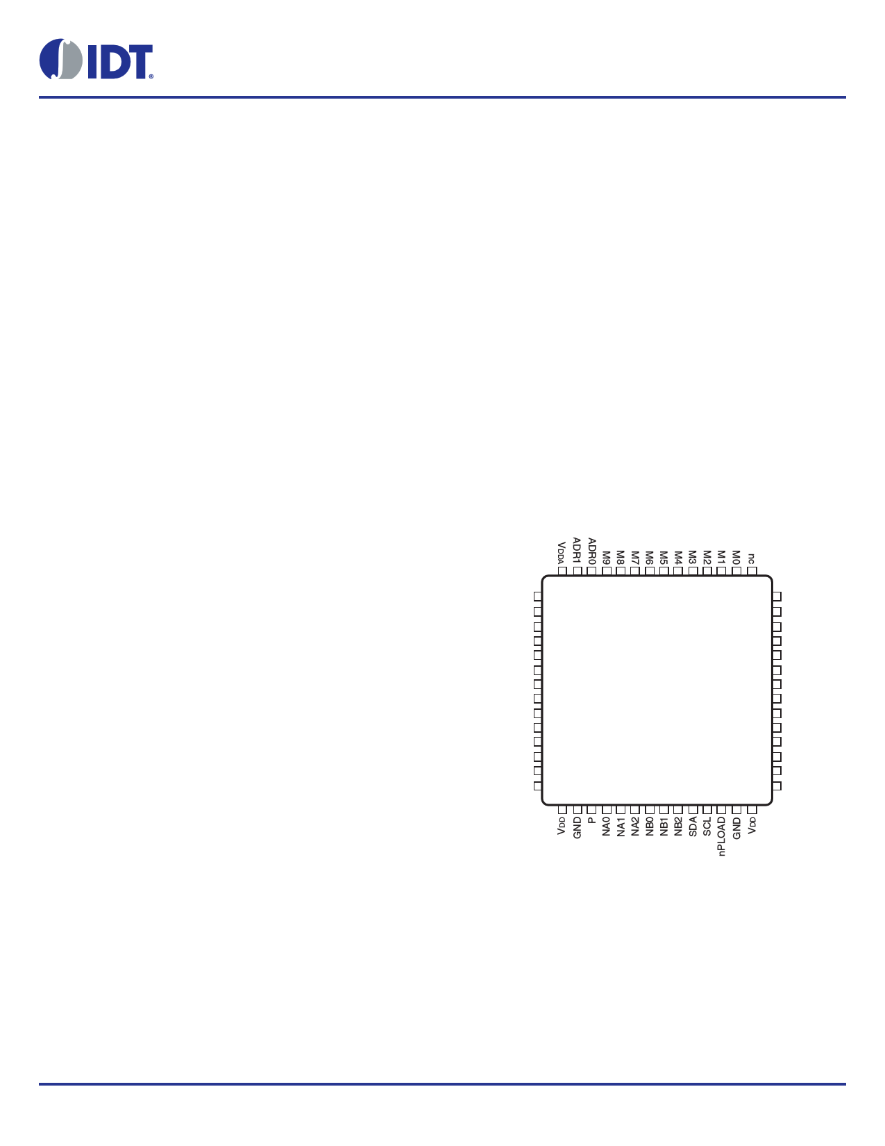
Pin Assignment
GND
nc
nBYPASS
nc
VDD
REF_CLK
GND
REF_SEL
XTAL_IN
XTAL_OUT
nMR
LOCK_DT
LEV_SEL
VDD
56 55 54 53 52 51 50 49 48 47 46 45 44 43
1 42
2 41
3 40
4 39
5 ICS844S42I 38
6 56-Lead VFQFN
7 8mm x 8mm x 0.925mm
8
9
package body
10 K Package
11 Top View
37
36
35
34
33
32
12 31
13 30
14 29
15 16 17 18 19 20 21 22 23 24 25 26 27 28
nc
VDDOA
VDDOA
QA
nQA
GND
GND
GND
GND
QB
nQB
VDDOB
VDDOB
nc
©2016 Integrated Device Technology, Inc
1
Revision A April 28, 2016
1 page 
844S42I Data Sheet
Device Configuration
The ICS844S42I supports an output frequency range of 81MHz to
2592MHz. The output frequency fOUT is a function of the reference
frequency fREF and the three internal PLL dividers P, M, and N. fOUT
can be represented by this formula:
fOUT = (fREF ÷ P) · M ÷ (NA, NB)
The M, N and P dividers require a configuration by the user to
achieve the desired output frequency. The output dividers NA, NB
determine the achievable output frequency range (see Table 3A).
The PLL feedback-divider M is the frequency multiplication factor
and the main variable for frequency synthesis. For a given reference
frequency fREF, the PLL feedback-divider M must be configured to
match the specified VCO frequency range in order to achieve a valid
PLL configuration:
fVCO = (fREF ÷ P) · M and 1296MHz fVCO 2592MHz
The output frequency may be changed at any time by changing the
value of the PLL feedback divider M. The smallest possible output
frequency change is the synthesizer granularity G (difference in fOUT
when incrementing or decrementing M). At a given reference
frequency, G is a function of the PLL pre-divider P and post-divider
N:
G = fREF ÷ (P · NA, NB)
The purpose of the PLL pre-divider P is to situate the PLL into the
specified VCO frequency range fVCO (in combination with M). For a
given output frequency, P = ÷4 results in a smaller output frequency
granularity G, P = ÷2 results a larger output frequency granularity G
and also decreases the PLL bandwidth compared to the P = ÷4
setting. The following example illustrates the output frequency range
of the 844S42I using a 16MHz reference frequency.
Table 3A. Device Configuration Table for fREF = 16MHz)
Output Frequency (MHz) NA, NB
M
P
1296 – 2592
324 – 648
4
1
162 – 324
2
648 – 1296
324 – 648
4
2
162 – 324
2
432 – 864
324 – 648
4
3
162 – 324
2
324 – 648
324 – 648
4
4
162 – 324
2
216 – 432
324 – 648
4
6
162 – 324
2
162 – 324
324 – 648
4
8
162 – 324
2
81 – 162
324 – 648
4
16
162 – 324
2
G (MHz)
4
8
2
4
1.33
2.66
1
2
0.66
1.33
0.5
1
0.25
0.5
©2016 Integrated Device Technology, Inc
5
Revision A April 28, 2016
5 Page 
844S42I Data Sheet
Table 4B. LVCMOS/LVTTL DC Characteristics, VDD = 3.3V ± 5%, TA = -40°C to 85°C
Symbol Parameter
Test Conditions
Minimum
VIH Input High Voltage
VIL Input Low Voltage
REF_CLK, nPLOAD,
LEV_SEL, ADR[1:0],
NA[0:2], NB[0:2], M1,
VDD = VIN = 3.465V
M2, M3, M7, M8,
IIH
Input High Current
nBYPASS
2.2
-0.3
M0, M4, M5, M6, M9,
P, nMR, SDA, SCL,
REF_SEL
VDD = VIN = 3.465V
REF_CLK, nPLOAD,
LEV_SEL, ADR[1:0],
NA[0:2], NB[0:2], M1,
VDD = 3.465V, VIN = 0V
M2, M3, M7, M8,
IIL
Input Low Current
nBYPASS
-10
M0, M4, M5, M6, M9,
P, nMR, SDA, SCL,
REF_SEL
VDD = 3.465V, VIN = 0V
-150
VOH Output High Voltage LOCK_DT
VOL Output Low Voltage LOCK_DT
IOH = -12mA
IOL = 12mA
2.6
Typical
Maximum
VDD + 0.3
0.8
150
10
0.5
Units
V
V
µA
µA
µA
µA
V
V
Table 4C. LVDS DC Characteristics, VDD = VDDOA = VDDOB = 3.3V ± 5%, TA = -40°C to 85°C
Symbol Parameter
Test Conditions
Minimum Typical
VOD
VOD
VOS
VOS
Differential Output Voltage
VOD Magnitude Change
Offset Voltage
VOS Magnitude Change
LEV_SEL = 0
LEV_SEL = 0
LEV_SEL = 0
LEV_SEL = 0
300 400
1.1 1.2
Maximum
500
50
1.3
50
Units
V
mV
V
mV
Table 4D. LVPECL DC Characteristics, VDD = VDDOA = VDDOB = 3.3V ± 5%, TA = -40°C to 85°C
Symbol Parameter
Test Conditions
Minimum Typical
VOH
VOL
VSWING
Output High Voltage; NOTE 1
Output Low Voltage; NOTE 1
Peak-to-Peak Output Voltage Swing
LEV_SEL = 1
LEV_SEL = 1
LEV_SEL = 1
VDDOx – 1.2
VDDOx – 2.0
0.6
NOTE 1: Outputs termination with 50 to VDDOx – 2V.
Maximum
VDDOx – 0.8
VDDOx – 1.4
1
Units
V
V
V
©2016 Integrated Device Technology, Inc
11
Revision A April 28, 2016
11 Page | ||
| Páginas | Total 28 Páginas | |
| PDF Descargar | [ Datasheet 844S42I.PDF ] | |
Hoja de datos destacado
| Número de pieza | Descripción | Fabricantes |
| 844S42I | Dual Output RF Frequency Synthesizer | IDT |
| Número de pieza | Descripción | Fabricantes |
| SLA6805M | High Voltage 3 phase Motor Driver IC. |
Sanken |
| SDC1742 | 12- and 14-Bit Hybrid Synchro / Resolver-to-Digital Converters. |
Analog Devices |
|
DataSheet.es es una pagina web que funciona como un repositorio de manuales o hoja de datos de muchos de los productos más populares, |
| DataSheet.es | 2020 | Privacy Policy | Contacto | Buscar |