|
|
|
PDF BM1P065FJ Data sheet ( Hoja de datos )
| Número de pieza | BM1P065FJ | |
| Descripción | PWM Control IC | |
| Fabricantes | ROHM Semiconductor | |
| Logotipo | ||
Hay una vista previa y un enlace de descarga de BM1P065FJ (archivo pdf) en la parte inferior de esta página. Total 30 Páginas | ||
|
No Preview Available !
Datasheet
AC/DC Drivers
PWM Control IC
BM1P065FJ
● General
The PWM control IC for AC/DC “BM1P065FJ”
provides an optimum system for all products that
include an electrical outlet.
A built-in start circuit that withstands 650 V helps to
keep power consumption low. Both isolated and
non-isolated versions are supported, making for
simpler design of various types of low-power
converters. Switching MOSFET and current detection
resistors are external devices, thus achieving a higher
degree of freedom in power supply design. The
switching frequency is set as fixed. Since current mode
control is used, a current limit is imposed in each cycle,
and excellent performance is demonstrated in
bandwidth and transient response. With a light load,
frequency is reduced and higher efficiency is realized.
A frequency hopping function is also built in,
contributing to low EMI.
Also on chip are soft start and burst functions, a
per-cycle overcurrent limiter, VCC overvoltage
protection, overload protection, and other protection
functions.
● Basic Specifications
Operating power supply voltage range: VCC 8.9 V to 26.0 V
VH: to 600 V
Operating current:
Normal: 0.60 mA (Typ.)
Burst mode: 0.35 mA (Typ.)
Oscillation frequency:
BM1P065FJ: 65 kHz (Typ.)
Operating temperature range:
-40°C to +85°C
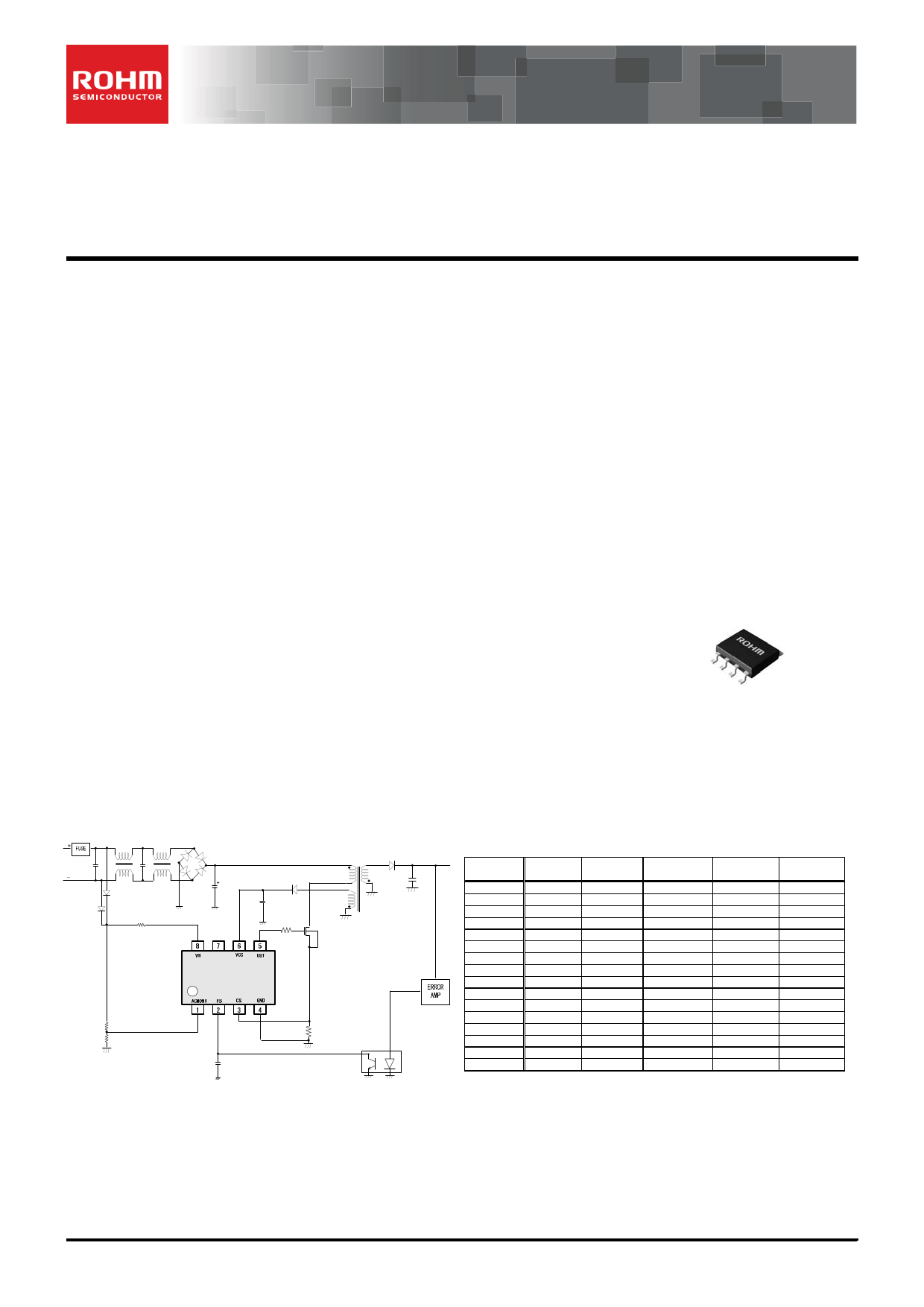
● Application circuit
● Features
PWM frequency: 65 kHz
PWM current mode method
Frequency hopping function
Burst operation during light load / Frequency
reduction function
650 V start circuit
VCC pin undervoltage protection
VCC pin overvoltage protection
CS pin open protection
CS pin Leading-Edge-Blanking function
Per-cycle overcurrent limiter function
Overcurrent limiter with AC voltage compensation
function
Soft start function
Secondary overcurrent protection circuit
● Package
SOP-J8
4.90 mm × 6.00 mm × 1.65 mm pitch 1.27 mm
(Typ.)
(Typ.) (Typ.)
(Typ.)
● Applications
AC adapters, TVs, and household appliances
(vacuum cleaners, humidifiers, air cleaners, air
conditioners, IH cooking heaters, rice cookers, etc.)
● Line-up
Frequency VCCOVP VCC recharge
BM1P061FJ
BM1P062FJ
BM1P063FJ
BM1P064FJ
BM1P065FJ
BM1P066FJ
BM1P067FJ
BM1P068FJ
BM1P101FJ
BM1P102FJ
BM1P103FJ
BM1P104FJ
BM1P105FJ
BM1P106FJ
BM1P107FJ
BM1P108FJ
65kHz
65kHz
65kHz
65kHz
65kHz
65kHz
65kHz
65kHz
100kHz
100kHz
100kHz
100kHz
100kHz
100kHz
100kHz
100kHz
Auto-restart
Latch
Auto-restart
Latch
Auto-restart
Latch
Auto-restart
Latch
Auto-restart
Latch
Auto-restart
Latch
Auto-restart
Latch
Auto-restart
Latch
〇
〇
〇
〇
×
×
×
×
〇
〇
〇
〇
×
×
×
×
X-cap
discharge
〇
〇
×
×
×
×
×
×
〇
〇
×
×
×
×
×
×
Brown-out
〇
〇
×
×
〇
〇
×
×
〇
〇
×
×
〇
〇
×
×
Figure 1.Application Circuit
○ Product structure:Silicon monolithic integrated circuit
.www.rohm.com
© 2013 ROHM Co., Ltd. All rights reserved.
TSZ22111・14・001
○This product is not designed for protection against radioactive rays
1/27
TSZ02201-0F2F0A200170-1-2
2.Oct.2013.Rev.001
1 page 
BM1P065FJ
● Block Diagram
Datasheet
Figure 3. Block Diagram
www.rohm.com
© 2013 ROHM Co., Ltd. All rights reserved.
TSZ22111・15・001
5/27
TSZ02201-0F2F0A200170-1-2
2.Oct.2013.Rev.001
5 Page 
BM1P065FJ
Datasheet
(4) ACMONI pin protection function
ACMONI(1pin) pin is for brown-out protection. When AC voltage falls, the brown-out function stops switching operation.
The usage is shown in Figure 13. The voltage divide AC voltage by resistors is applied to ACMONI pin.
When ACMONI pin voltage exceeds VACOMONI (1.0Vtyp), IC detects normal state, and IC starts switching operation.
When ACMONI pin voltage is lower than VACMONI(0.7V typ) after switching operation, the internal timer of IC starts to
operate. When the status which ACMONI pin voltage is lower than VACMONI(0.7V typ) continues for TACMONI1(typ=256ms),
the switching operation stops.
For that, even if AC voltage temporary disappearance occurs, the switching operation continues within TACMONI1(typ=256ms)
period.
RH
RL
Figure 13. Application circuit
The detection value of brown-out sets by external resistors of AMMONI pin.
The setting method is below:
○The setting : When AC line voltage is higher than the voltage “VHstart”, IC starts to operate
VHstart value is calculated by below equation.
VHstart=(RH+RL)/RL×VACMONI1
*VACMONI1=1.0V
Please set RH and RL by the equation.
Then brown-out protection voltage “VHend” is calculated by below equation.
VHend=(RH+RL)/RL×VACMONI2
*VACMONI1=0.7V
When brown-out function does not use, ACMONI pin voltage needs to be set the voltage from 1.3V to 5.0V
As the applied method, apply from outside or apply the voltage divided resistors from VCC.
Vout
Np Ns
Nb
Figure 14. The setting of ACMONI pin in the case not to use brown-out function
www.rohm.com
© 2013 ROHM Co., Ltd. All rights reserved.
TSZ22111・15・001
11/27
TSZ02201-0F2F0A200170-1-2
2.Oct.2013.Rev.001
11 Page | ||
| Páginas | Total 30 Páginas | |
| PDF Descargar | [ Datasheet BM1P065FJ.PDF ] | |
Hoja de datos destacado
| Número de pieza | Descripción | Fabricantes |
| BM1P065FJ | PWM Control IC | ROHM Semiconductor |
| Número de pieza | Descripción | Fabricantes |
| SLA6805M | High Voltage 3 phase Motor Driver IC. |
Sanken |
| SDC1742 | 12- and 14-Bit Hybrid Synchro / Resolver-to-Digital Converters. |
Analog Devices |
|
DataSheet.es es una pagina web que funciona como un repositorio de manuales o hoja de datos de muchos de los productos más populares, |
| DataSheet.es | 2020 | Privacy Policy | Contacto | Buscar |