|
|
|
PDF DAC-08 Data sheet ( Hoja de datos )
| Número de pieza | DAC-08 | |
| Descripción | 8-Bit High-Speed Multiplying D/A Converter | |
| Fabricantes | ON Semiconductor | |
| Logotipo | ||
Hay una vista previa y un enlace de descarga de DAC-08 (archivo pdf) en la parte inferior de esta página. Total 14 Páginas | ||
|
No Preview Available !
DAC−08 SERIES
8−Bit High−Speed
Multiplying D/A Converter
The DAC-08 series of 8-bit monolithic multiplying Digital-to-
Analog Converters provide very high-speed performance coupled
with low cost and outstanding applications flexibility.
Advanced circuit design achieves 70 ns settling times with very
low glitch and at low power consumption. Monotonic multiplying
performance is attained over a wide 20-to-1 reference current range.
Matching to within 1 LSB between reference and full-scale currents
eliminates the need for full-scale trimming in most applications.
Direct interface to all popular logic families with full noise immunity
is provided by the high swing, adjustable threshold logic inputs.
Dual complementary outputs are provided, increasing versatility
and enabling differential operation to effectively double the peak-to-
peak output swing. True high voltage compliance outputs allow
direct output voltage conversion and eliminate output op amps in
many applications.
All DAC-08 series models guarantee full 8-bit monotonicity and
linearities as tight as 0.1% over the entire operating temperature
range. Device performance is essentially unchanged over the
"4.5 V to "18 V power supply range, with 37 mW power
consumption attainable at "5.0 V supplies.
The compact size and low power consumption make the DAC-08
attractive for portable and military aerospace applications.
Features
• Fast Settling Output Current − 70 ns
• Full-Scale Current Prematched to "1.0 LSB
• Direct Interface to TTL, CMOS, ECL, HTL, PMOS
• Relative Accuracy to 0.1% Maximum Overtemperature Range
• High Output Compliance −10 V to +18 V
• True and Complemented Outputs
• Wide Range Multiplying Capability
• Low FS Current Drift − "10ppm/°C
• Wide Power Supply Range − "4.5 V to "18 V
• Low Power Consumption − 37 mW at "5.0 V
• Pb−Free Packages are Available*
Applications
• 8-Bit, 1.0 ms A-to-D Converters
• Servo-Motor and Pen Drivers
• Waveform Generators
• Audio Encoders and Attenuators
• Analog Meter Drivers
• Programmable Power Supplies
• CRT Display Drivers
• High-Speed Modems
• Other Applications where Low Cost, High Speed and Complete
Input/Output Versatility are Required
• Programmable Gain and Attenuation
• Analog-Digital Multiplication
*For additional information on our Pb−Free strategy and soldering details, please
download the ON Semiconductor Soldering and Mounting Techniques Reference
Manual, SOLDERRM/D.
© Semiconductor Components Industries, LLC, 2005
October, 2005 − Rev. 1
1
http://onsemi.com
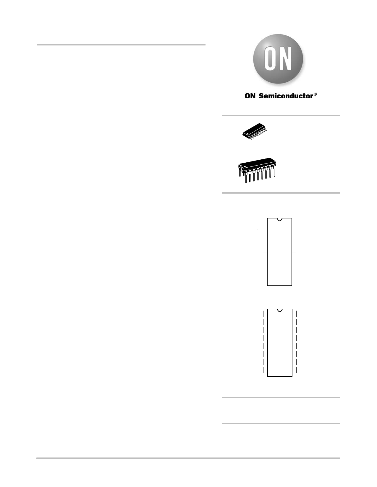
16
1
SOIC−16
D SUFFIX
CASE 751B
16
1
PDIP−16
N SUFFIX
CASE 648
PIN CONNECTIONS
N Package
VLC 1
IO 2
V− 3
IO 4
B1 (MSB) 5
B2 6
B3 7
B4 8
16 COMPEN
15 VREF−
14 VREF+
13 V+
12 B8 (LSB)
11 B7
10 B6
9 B5
(Top View)
D Package*
V+ 1
VREF+ 2
VREF− 3
COMPEN 4
VLC 5
IO 6
V− 7
IO 8
16 B8 (LSB)
15 B7
14 B6
13 B5
12 B4
11 B3
10 B2
9 B1 (MSB)
(Top View)
*SO and non−standard pinouts.
ORDERING INFORMATION
See detailed ordering and shipping information in the package
dimensions section on page 13 of this data sheet.
DEVICE MARKING INFORMATION
See general marking information in the device marking
section on page 13 of this data sheet.
Publication Order Number:
DAC−08/D
1 page 
DAC−08 SERIES
AC ELECTRICAL CHARACTERISTICS
DAC−08C
DAC−08E
DAC−08H
Characteristic
Symbol Test Conditions Min Typ Max Min Typ Max Min Typ Max
Settling Time
tS To "1/2LSB, All − 70 135 − 70 135 − 70 135
Bits Switched On or
Off, Tamb = 25°C
Propagation Delay
Low-to-High
High-to-Low
tPLH
Tamb = 25°C,
Each Bit
tPHL All Bits Switched − 35 60 − 35 60 − 35 60
Unit
ns
ns
TEST CIRCUITS
VREF
V− V+
RREF
R15
16
14
15
3 13
DAC-08
4
5-12 1 2
CONTROL
LOGIC
Rf
−
NE5534
+
REFERENCE DAC
ACCURACY > 0.006%
Figure 2. Relative Accuracy Test Circuit
ERROR
OUTPUT
0.1 mF VCC
13
5
6 14
+2.0 VDC
1.0 kW
2.4 V
eIN 0.4 V
1.0 V
1.4 V
tPHL = tPLH = 10 ns
USE RL to GND
FOR TURN OFF
7 15
0.1 mF
SETTLING TIME
MEASUREMENT
81
9 DAC-08 2
1.0 kW RL
FOR SETTLING TIME
RL = 500 W
10 4
MEASUREMENT
0
11 16
eO (ALL BITS
SWITCHED LOW
tS = 70 ns TYPICAL
eIN 12
TO HIGH)
TO ±1/2 LSB
51 W
0.1 mF
3
15 pF
CO ≤ 25 pF
TRANSIENT 0
RESPONSE
-100 mV
RL = 50 W
PIN 4 TO GND
VEE
tPLH
tPHL
Figure 3. Transient Response and Settling Time
http://onsemi.com
5
5 Page 
DAC−08 SERIES
VREF
R1
R2
14
15
R3
DAC-08
NOTES:
R1 = low T.C.
R3 = R1 + R2
R2 ≈ 0.1 R1 to minimize pot. contribution to full-scale drift
4
2
R4 = 1MW
V+ V−
RS = 20kW
Figure 26. Recommended Full−Scale and Zero−Scale Adjust
IR = 2mA
14
15
DAC-08
4
2
5kW (LOW T.C.)
−
NE531
OR
EQUIV
+
5kW
VOUT =
0 TO +10V
Figure 27. Unipolar Voltage Output for Low Impedance Output
http://onsemi.com
11
11 Page | ||
| Páginas | Total 14 Páginas | |
| PDF Descargar | [ Datasheet DAC-08.PDF ] | |
Hoja de datos destacado
| Número de pieza | Descripción | Fabricantes |
| DAC-02 | (DAC-0x) 10-Bit Plus Sign Voltage Output D/A Converters | Precision Monolithics |
| DAC-03 | (DAC-0x) 10-Bit Plus Sign Voltage Output D/A Converters | Precision Monolithics |
| DAC-05 | (DAC-0x) 10-Bit Plus Sign Voltage Output D/A Converters | Precision Monolithics |
| DAC-08 | 8-Bit High-Speed Multiplying D/A Converter | ON Semiconductor |
| Número de pieza | Descripción | Fabricantes |
| SLA6805M | High Voltage 3 phase Motor Driver IC. |
Sanken |
| SDC1742 | 12- and 14-Bit Hybrid Synchro / Resolver-to-Digital Converters. |
Analog Devices |
|
DataSheet.es es una pagina web que funciona como un repositorio de manuales o hoja de datos de muchos de los productos más populares, |
| DataSheet.es | 2020 | Privacy Policy | Contacto | Buscar |