|
|
|
PDF ADM1033 Data sheet ( Hoja de datos )
| Número de pieza | ADM1033 | |
| Descripción | Thermal Monitor and Fan Speed (RPM) Controller | |
| Fabricantes | Analog Devices | |
| Logotipo | ||
Hay una vista previa y un enlace de descarga de ADM1033 (archivo pdf) en la parte inferior de esta página. Total 30 Páginas | ||
|
No Preview Available !
Thermal Monitor and
www.DataSheet4U.com
Fan Speed (RPM) Controller
ADM1033
FEATURES
1 local and 1 remote temperature channel
±1.5°C accuracy on local and remote channels
Automatic series resistance cancellation on remote
Temperature channels > 1 kΩ
Fast (up to 64 measurements per second)
SMBus 2.0, 1.1, and 1.0 compliant
SMBus address input/LOCATION input to UDID
Programmable over-/undertemperature limits
Programmable fault queue
SMBusALERT output
Fail-safe overtemperature comparator output
Fan speed (RPM) controller
Look-up table for temperature-to-fan-speed control
Linear and discrete options for look-up table
FAN_FAULT output
THERM input, used to time PROCHOT assertions
REF input, used as reference for THERM (PROCHOT)
3 V to 5.5 V supply
Small 16-lead QSOP package
APPLICATIONS
Desktop and notebook PCs
Embedded systems
Telecommunications equipment
LCD projectors
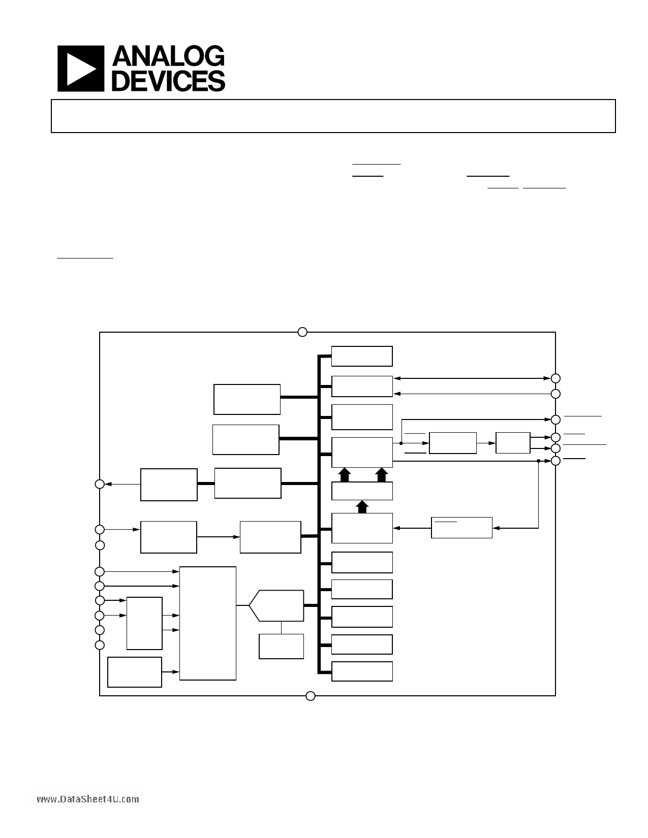
FUNCTIONAL BLOCK DIAGRAM
VCC
6
ADM1033
MANUAL FAN
SPEED CONTROL
REGISTERS
TEMPERATURE-TO-
FAN-SPEED
LOOK-UP TABLE
SMBUS
ADDRESS
SERIAL BUS
INTERFACE
ADDRESS
POINTER
REGISTER
STATUS
REGISTER
ALERT
THERM
MASK
REGISTERS
FAULT
QUEUE
16 SCL
15 SDA
8 FAN_FAULT
3 ALERT Comp
14 SMBusALERT
7 THERM
DRIVE 1
FAN SPEED
CONTROLLER
FAN RESPONSE
LIMIT
COMPARATOR
TACH 2
NC 4
TACH SIGNAL
CONDITIONING
REF 8
LOCATION 13
D– 9
D+ 10
NC 11
NC 12
SRC
BLOCK
BAND GAP
TEMPERATURE
SENSOR
ANALOG
MULTIPLEXER
NC = NO CONNECT
FAN
SPEED
COUNTER
ADC
VALUE AND
LIMIT
REGISTERS
FAULT
QUEUE
HYSTERESIS
REGISTERS
OFFSET
REGISTERS
BAND GAP
REFERENCE
CONVERSION
RATE REGISTER
CONFIGURATION
REGISTERS
5
GND
Figure 1.
THERM PERCENT
TIMER
Rev. 0
Information furnished by Analog Devices is believed to be accurate and reliable.
However, no responsibility is assumed by Analog Devices for its use, nor for any
infringements of patents or other rights of third parties that may result from its use.
Specifications subject to change without notice. No license is granted by implication
or otherwise under any patent or patent rights of Analog Devices. Trademarks and
registered trademarks are the property of their respective owners.
One Technology Way, P.O. Box 9106, Norwood, MA 02062-9106, U.S.A.
Tel: 781.329.4700
www.analog.com
Fax: 781.326.8703 © 2004 Analog Devices, Inc. All rights reserved.
1 page 
Parameter
TACHOMETER ACCURACY
Fan Speed Measurement Accuracy
AGTL + INPUT (THERM)
Input High Level
Input Low Level
SERIAL BUS TIMING3
Clock Frequency, fSCLK
Glitch Immunity, tSW
Bus Free Time, tBUF
Start Setup Time, tSU:STA
Start Hold Time, tHD:STA
Stop Condition Setup Time, tSU:STO
SCL Low Time, tLOW
SCL High Time, tHIGH
SCL, SDA Rise Time, tr
SCL, SDA Fall Time, tf
Data Setup Time, tSU:DAT
Detect Clock Low Timeout, tTIMEOUT
Min Typ
Max Units
±4 %
0.75 × REF
0.4
V
V
50
1.3
0.6
0.6
0.6
1.3
0.6
100
25
400
1000
300
35
kHz
ns
µs
µs
µs
µs
µs
µs
ns
ns
ns
ms
ADM1033www.DataSheet4U.com
Test Conditions/Comments
See Figure 2
See Note 4
1 Typicals are at TA = 25°C and represent most likely parametric norm. Standby current typ is measured with VCC = 3.3 V. Timing specifications are tested at logic levels of
VIL = 0.8 V for a falling edge and VIH = 2.1 V for a rising edge.
2 Operation at 5.5 V is guaranteed by design, not production tested.
3 Guaranteed by design, not production tested.
4 SMBus timeout disabled by default. See the SMBus Timeout section for more information.
SCL
tLOW tR
tHD:STA
tHD:DAT
SDA
tBUF
PS
tF
tHIGH
tSU:DAT
tHD:STA
tSU:STA
S
Figure 2. Serial Bus Timing Diagram
tSU:STO
P
Rev. 0 | Page 5 of 40
5 Page 
ADM1033www.DataSheet4U.com
Table 4. Internal Register Descriptions
Register
Description
Configuration
Provides control and configuration of various functions on the device.
Conversion Rate
Determines the number of measurements per second completed by the ADM1033.
Address Pointer
Contains the address that selects one of the other internal registers. When writing to the ADM1033, the first byte
of data is always a register address, which is written to the address pointer register.
Status
Provides the status of each limit comparison.
Interrupt Mask
Allows the option to mask ALERTs due to particular out-of-limit conditions.
Value and Limit
Stores the results of temperature and fan speed measurements, along with their limit values.
Offset
Allows the local and remote temperature channel readings to be offset by a twos complement value written to
them. These values are automatically added to the temperature values (or subtracted from them if negative). This
allows the systems designer to optimize the system, if required, by adding or subtracting up to 15.875°C from a
temperature reading.
THERM Limit and
Contains the temperature value at which THERM is asserted and determines the level of hysteresis.
Hysteresis
Look-Up Table
Used to program the look-up table for the fan-speed-to-temperature profile.
THERM % Ontime and Reflects the state of the THERM input and monitors the duration of the assertion time of the signal as a
THERM % Limit
percentage of a time window. The user can program the length of the time window.
Table 5. Resistor Ratios for Setting LOCATION Bits
Ideal Ratio R2/(R1 + R2) R1 (kΩ) R2 (kΩ) Actual R2/(R1 + R2)
N/A 0 O/C 1
0.8125
18 82 0.82
0.6875
22 47 0.6812
0.5625
12 15 0.5556
0.4375
15 12 0.4444
0.3125
47 22 0.3188
0.1875
82 18 0.18
N/A
O/C 0
0
Error (%)
0
+0.75
−0.63
−0.69
+0.69
+0.63
−0.75
0
SMBus Mode
ARP1
ARP1
ARP1
ARP1
FD1
FD1
FD1
FD1
SMBus Address
N/A
N/A
N/A
N/A
0x53
0x52
0x51
0x50
UDID LLL
111
110
101
100
N/A
N/A
N/A
N/A
1 FD denotes fixed-and-discoverable mode, ARP denotes ARP-capable mode.
Table 6. UDID Values
Bit No.
Name
<127:120>
Device Capabilities
<1119:112>
<111:96>
Version/Revision:
Vendor ID
<95:80>
Device ID
<79:64>
Interface
<63:48>
Subsystem Vendor ID
<47:32>
Subsystem Device ID
<31:0>
Vendor-Specific ID
Function
Describes the ADM1033’s capabilities (for instance, that it supports PEC
and uses a random number address device)
UDID version number (Version 1) and silicon revision identification
Vendor ID number, assigned by the SBS Implementer’s Forum or the
PCI SIG
Device ID
Identifies the protocol layer interfaces supported by the ADM1033. This
represents SMBus 2.0 as the Interface version.
Subsystem Vendor ID = 0 (subsystem fields are unsupported)
Subsystem Device ID = 0 (subsystem fields are unsupported)
A unique number per device. Contains the LOCATION Information (LLL)
and a 16-bit random number (x). See Table 5 for information on setting
the LLL bits.
Value
11000001
00001010
00010001
11010100
00010000
00110011
00000000
00000100
00000000
00000000
00000000
00000000
00000000
00000LLL
xxxxxxxx
xxxxxxxx
Rev. 0 | Page 11 of 40
11 Page | ||
| Páginas | Total 30 Páginas | |
| PDF Descargar | [ Datasheet ADM1033.PDF ] | |
Hoja de datos destacado
| Número de pieza | Descripción | Fabricantes |
| ADM1030 | Intelligent Temperature Monitor and PWM Fan Controller | Analog Devices |
| ADM1030 | Intelligent Temperature Monitor and PWM Fan Controller | ON Semiconductor |
| ADM1031 | Intelligent Temperature Monitor and Dual PWM Fan Controller | Analog Devices |
| ADM1031 | Intelligent Temperature Monitor and Dual PWM Fan Controller | ON Semiconductor |
| Número de pieza | Descripción | Fabricantes |
| SLA6805M | High Voltage 3 phase Motor Driver IC. |
Sanken |
| SDC1742 | 12- and 14-Bit Hybrid Synchro / Resolver-to-Digital Converters. |
Analog Devices |
|
DataSheet.es es una pagina web que funciona como un repositorio de manuales o hoja de datos de muchos de los productos más populares, |
| DataSheet.es | 2020 | Privacy Policy | Contacto | Buscar |