|
|
|
PDF ZL2004 Data sheet ( Hoja de datos )
| Número de pieza | ZL2004 | |
| Descripción | Adaptive Digital DC-DC Controller | |
| Fabricantes | Intersil Corporation | |
| Logotipo | ||
Hay una vista previa y un enlace de descarga de ZL2004 (archivo pdf) en la parte inferior de esta página. Total 30 Páginas | ||
|
No Preview Available !
Data Sheet
ZL2004
www.DataSheet4U.com
February 18, 2009
FN6846.0
Adaptive Digital DC-DC Controller with Current Sharing
Description
The ZL2004 is a digital DC-DC controller designed to
work with the ZL1505 MOSFET driver IC. Current
sharing allows multiple devices to be connected in
parallel to source loads with very high current
demands. Adaptive performance optimization
algorithms improve power conversion efficiency across
the entire load range. Zilker Labs Digital-DC™
technology enables a blend of power conversion
performance and power management features.
The ZL2004 is designed to be a flexible building block
for DC power and can be easily adapted to designs
ranging from a single-phase power supply operating
from a 4.5 V input to a multi-phase supply operating
from a 12V input. The ZL2004 eliminates the need for
complicated power supply managers as well as
numerous external discrete components.
All operating features can be configured by simple pin-
strap/resistor selection or through the SMBus™ serial
interface. The ZL2004 uses the PMBus™ protocol for
communication with a host controller and the Digital-
DC bus for communication between other Zilker Labs
devices.
Features
Power Conversion
• Efficient synchronous buck controller
• Adaptive performance optimization algorithms
• 4.5 V to 14 V input range
• 0.54 V to 4 V output range (with margin)
• ± 1% VOUT set-point accuracy
• Fast load transient response
• Current sharing and phase interleaving
• Digitally adjustable current sense range
• Snapshot™ parameter capture
• RoHS compliant (5 x 5 mm) QFN package
Power Management
• Digital soft start/stop
• Precision delay and ramp-up
• Power good/enable
• Voltage tracking, sequencing and margining
• Voltage/current/temperature monitoring
• SMBus communication (PMBus compliant)
• Output voltage and current protection
• Internal non-volatile memory (NVM)
Applications
• Servers / storage equipment
• Telecom / datacom equipment
• Power supplies (memory, DSP, ASIC, FPGA)
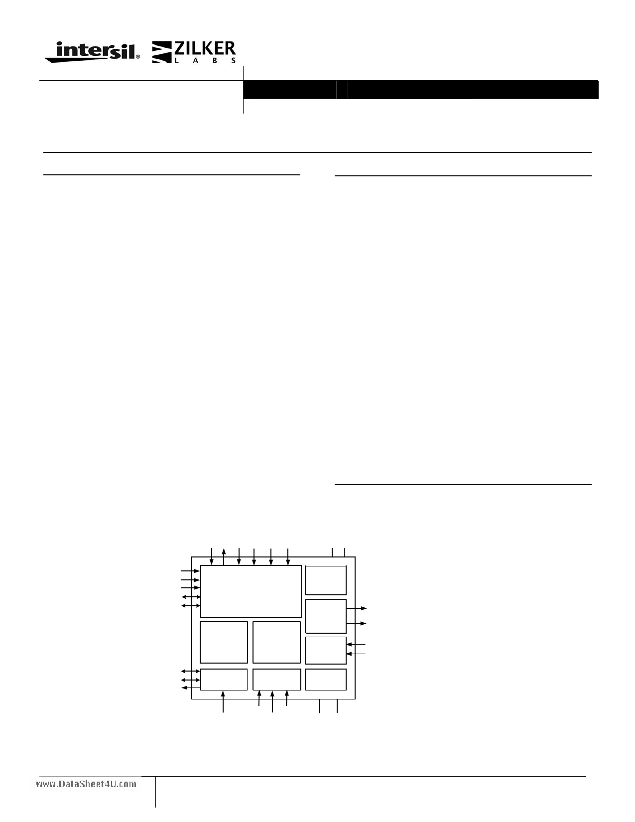
EN PG SS FC ILIM CFG
V25 VR VDD
V (0,1)
VMON
MGN
SYNC
DDC
SCL
SDA
SALRT
POWER
MANAGEMENT
NON-
VOLATILE
MEMORY
I2 C
PWM
CONTROLLER
MONITOR
ADC
LDO
LEVEL
SHIFTER
CURRENT
SENSE
TEMP
SENSOR
PWMH
PWML
ISENA
ISENB
SA (0,1)
VTRK VSEN+/-
XTEMP
SGND DGND
Figure 1. Block Diagram
1 1-888-INTERSIL or 1-888-468-3774|Intersil (and design) is a registered trademark of Intersil Americas Inc.
Copyright © Intersil Americas Inc. 2009. All Rights Reserved
All other trademarks mentioned are the property of their respective owners
1 page 
ZL2004
www.DataSheet4U.com
Table 3. Electrical Characteristics (continued)
VDD = 12 V, TA = -40°C to 85°C unless otherwise noted. Typical values are at TA = 25°C.
Parameter
Conditions
Min Typ
Oscillator and Switching Characteristics
Switching frequency range
Switching frequency set-point accuracy
Maximum PWM duty cycle
Minimum SYNC pulse width
Input clock frequency drift tolerance
Factory default
External clock source
200 –
-5 –
95 –
150 –
- 13 –
Tracking
VTRK input bias current
VTRK tracking ramp accuracy
VTRK regulation accuracy
VTRK = 4.0 V
100% Tracking, VOUT - VTRK
100% Tracking, VOUT - VTRK
–
- 100
-1
110
–
–
Fault Protection Characteristics
UVLO threshold range
UVLO set-point accuracy
UVLO hysteresis
UVLO delay
Power good VOUT low threshold
Power good VOUT high threshold
Power good VOUT hysteresis
Power good delay
VSEN undervoltage threshold
VSEN overvoltage threshold
VSEN undervoltage hysteresis
VSEN undervoltage/ overvoltage fault
response time
Current limit set-point accuracy
(VOUT referenced)
Current limit protection delay
Temperature compensation of
current limit protection threshold
Thermal protection threshold (junction
temperature)
Thermal protection hysteresis
Configurable via I2C/SMBus
Factory default
Configurable via I2C/SMBus
Factory default
Factory default
Factory default
Using pin-strap or resistor 7
Configurable via I2C/SMBus
Factory default
Configurable via I2C/SMBus
Factory default
Configurable via I2C/SMBus
Factory default
Configurable via I2C/SMBus
Factory default
Configurable via I2C/SMBus
Factory default
Configurable via I2C/SMBus
Factory default
Configurable via I2C/SMBus
2.85
- 150
–
0
–
–
–
–
2
0
–
0
–
0
–
–
5
–
–
1
100
–
- 40
–
–
–
3
–
–
90
115
5
–
–
85
–
115
–
5
16
–
±10
5
–
4400
125
–
15
Notes:
7. Factory default Power Good delay is set to the same value as the soft start ramp time.
8. Percentage of Full Scale (FS) with temperature compensation applied.
9. tSW = 1/fSW, where fSW is the switching frequency.
Max Unit
1400
5
–
–
13
kHz
%
%
ns
%
200
+ 100
1
µA
mV
%
16
150
–
100
2.5
–
–
–
20
500
–
110
–
115
–
–
60
–
–
32
12700
–
125
–
V
mV
%
%
µs
% VOUT
% VOUT
%
ms
s
% VOUT
% VOUT
% VOUT
% VOUT
% VOUT
µs
µs
% FS8
tSW 9
tSW 9
ppm /
°C
°C
°C
°C
5 Data Sheet Revision 2/18/2009
www.intersil.com
5 Page 
ZL2004
www.DataSheet4U.com
and adaptive frequency are available to provide greater
efficiency improvement.
The ZL2004 can also be used with a single-ended
MOSFET driver. Simple parameter changes allow the
device to use a single PWM to drive the logic input of
such drivers. The trade-offs for using this mode may
include reduced efficiency, reduced ramp-up timing
accuracy, and degraded pre-bias protection.
Table 5. Multi-mode Pin Configuration
Pin Tied To
LOW
(Logic LOW)
Value
< 0.8 VDC
OPEN
(N/C)
No connection
HIGH
(Logic HIGH)
> 2.0 VDC
Resistor to SGND
Set by resistor value
4.3 Power Management Overview
The ZL2004 incorporates a wide range of configurable
power management features that are simple to
implement with no external components. Additionally,
the ZL2004 includes circuit protection features that
continuously safeguard the device and load from
damage due to unexpected system faults. The ZL2004
can continuously monitor input voltage, output
voltage/current, internal temperature, and the
temperature of an external thermal diode. A Power
Good output signal is also included to enable power-on
reset functionality for an external processor.
All power management functions can be configured
using either pin configuration techniques (see Figure 6)
or via the I2C/SMBus interface. Monitoring parameters
can also be pre-configured to provide alerts for specific
conditions. See Application Note AN33 for more
details on SMBus monitoring.
4.4 Multi-mode Pins
In order to simplify circuit design, the ZL2004
incorporates patented multi-mode pins that allow the
user to easily configure many aspects of the device
with no programming. Most power management
features can be configured using these pins. The multi-
mode pins can respond to four different connections as
shown in Table 5. These pins are sampled when power
is applied or by issuing a PMBus Restore command
(See Application Note AN33).
Pin-strap Settings: This is the simplest implementation
method, as no external components are required. Using
this method, each pin can take on one of three possible
states: LOW, OPEN, or HIGH. These pins can be
connected to the V25 pin for logic HIGH settings as
this pin provides a regulated voltage higher than 2 V.
Using a single pin, one of three settings can be
selected. Using two pins, one of nine settings can be
selected.
Figure 6. Pin-strap and Resistor Setting Examples
Resistor Settings: This method allows a greater range
of adjustability when connecting a finite value resistor
(in a specified range) between the multi-mode pin and
SGND. Standard 1% resistor values are used, and only
every fourth E96 resistor value is used so the device
can reliably recognize the value of resistance
connected to the pin while eliminating the error
associated with the resistor accuracy. Up to 31 unique
selections are available using a single resistor.
I2C/SMBus Method: Almost any ZL2004 function can
be configured via the I2C/SMBus interface using
standard PMBus commands. Additionally, any value
that has been configured using the pin-strap or resistor
setting methods can also be re-configured and/or
verified via the I2C/SMBus. See Application Note
AN33 for more details.
The SMBus device address and VOUT_MAX are the
only parameters that must be set by external pins. All
other device parameters can be set via the I2C/SMBus.
The device address is set using the SA0 and SA1 pins.
VOUT_MAX is determined as 10% greater than the
voltage set by the V0 and V1 pins.
11 Data Sheet Revision 2/18/2009
www.intersil.com
11 Page | ||
| Páginas | Total 30 Páginas | |
| PDF Descargar | [ Datasheet ZL2004.PDF ] | |
Hoja de datos destacado
| Número de pieza | Descripción | Fabricantes |
| ZL2004 | Adaptive Digital DC-DC Controller | Intersil Corporation |
| ZL2004-01 | Adaptive Digital DC-DC Controller | Intersil Corporation |
| ZL2005 | Digital-DC Integrated Power Management and Conversion IC | Intersil Corporation |
| ZL2005P | Digital-DC Controller | Intersil Corporation |
| Número de pieza | Descripción | Fabricantes |
| SLA6805M | High Voltage 3 phase Motor Driver IC. |
Sanken |
| SDC1742 | 12- and 14-Bit Hybrid Synchro / Resolver-to-Digital Converters. |
Analog Devices |
|
DataSheet.es es una pagina web que funciona como un repositorio de manuales o hoja de datos de muchos de los productos más populares, |
| DataSheet.es | 2020 | Privacy Policy | Contacto | Buscar |