|
|
|
PDF CT19901 Data sheet ( Hoja de datos )
| Número de pieza | CT19901 | |
| Descripción | MIL-STD-1553B Remote Terminal/ Bus Controller/ or Passive Monitor Hybrid with Status Word Control | |
| Fabricantes | Aeroflex Circuit Technology | |
| Logotipo | ||
Hay una vista previa y un enlace de descarga de CT19901 (archivo pdf) en la parte inferior de esta página. Total 29 Páginas | ||
|
No Preview Available !
CT1990/1 Series
MIL-STD-1553B Remote Terminal, Bus Controller,
or Passive Monitor Hybrid with Status Word Control
Features
• Performs the Complete Dual-Redundant Remote Terminal, Bus Controller Protocol
and Passive Monitor Functions of MIL-STD-1553B
• Automated Self-Test Functions
• Allows setting of the Message Error Bit on illegal commands
• Provides programmable control over Terminal Flag and Subsystem Flag Status Bits
• MIL-PRF-38534 Compliant Circuits Available
• 50 mw Typical Power Consumption
• Small Size
• Available in Ceramic Plug-in Package Configuration
• Compatible with all ACT Driver/Receiver Units
CIRCUIT TECHNOLOGY
• 5V DC Operation
• Full Military (-55°C to +125°C) Temperature Range
• DESC SMD# 5962–94775: Released CT1990, Pending CT1991
1
General Description
The CT1990/1 Series is a monolithic implementation of the MIL-STD-1553B Bus Controller, Remote
Terminal and Passive Monitor functions. All protocol functions of MIL-STD-1553B are incorporated and a
number of options are included to improve flexibility. These features include programming of the status
word, illegalizing specific commands and an independent loop back self-test which is initiated by the
subsystem. This unit is directly compatible with all transceivers and microprocessor interfaces such as the
CT1611 and CT1800 produced by Aeroflex Incorporated.
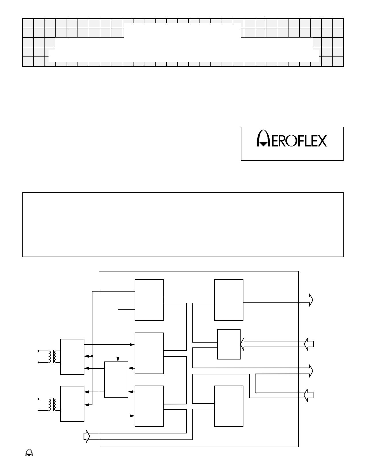
Block Diagram (With Transformers)
Encoder
Interface
Unit
Sub Address
&
Word Count
Outputs
BUS "0"
T/R
Hybrid
BUS "1"
T/R
Hybrid
Driver
Select
&
Enable
Decoder
"O"
Decoder
"1"
Status
Word
Control
Internal
Highway
Control
Program
Inputs
Discrete
Outputs
Control
Inputs
Terminal
Address
Inputs
CT1990/1
eroflex Circuit Technology – Data Bus Modules For The Future © SCD1990 REV B 8/21/00
1 page 
Synchronize Mode Commands
Once the RT has validated the command word and checked for the correct address, the SYNC line is set low.
The signal WC4 will be set low for a Synchronize mode command (See Figure 16), and high for a Synchronize
with data word mode command (See Figure 15). In a Synchronize with data word mode command, SYNC
remains low during the time that the data word is received. Once the data word has been validated, it is passed
to the subsystem on the internal highway IH08-IH715 in two bytes using IUSTB as a strobe signal and H/L as
the byte indicator (high byte first followed by low byte). SYNC being low should be used on the enable to allow
IUSTB to clock synchronize mode data to the subsystem.
If the subsystem does not need to implement either of these mode commands, the SYNC signal can be ignored,
since the RT requires no response from the subsystem.
Transmit Vector Word Mode Command
Figure 14 illustrates the relevant signal timings for an RT receiving a valid Transmit Vector Word mode
command. The RT requests data by setting VECTEN low. The subsystem should use H/L to enable first the high
byte and then the low byte of the Vector word onto the internal highway IH08-IH715.
It should be noted that the RT expects the Vector word contents to be already prepared in a latch ready for
enabling onto the internal highway when VECTEN goes low. If the subsystem has not been designed to handle
the Vector word mode command, it will be the fault of the Bus Controller if the RT receives such a command.
Since the subsystem is not required to acknowledge the mode command, the RT will not be affected in any way
by Vector word circuitry not being implemented in the subsystem. It will however transmit a data word as the
Vector word, but this word will have no meaning.
Reset Mode Command
Figure 8 shows the relevant signal timings for an RT receiving a valid reset mode command. Once the command
word has been fully validated and serviced, the RESET signal is pulsed low. This signal may be used as a reset
function for subsystem interface circuitry.
Dynamic Bus Allocation
This mode command is intended for use with a terminal which has the capability of configuring itself into a bus
controller on command from the bus. The line DBCREQ cannot go true unless the DBCACC line was true at the
time of the valid command, i.e. tied low. For terminals acting only as RTs, the signal DBCACC should be tied
high (inactive), and the signal DBCREQ should be ignored and left unconnected.
Use of the Busy Status Bit
The Busy Bit is used by the subsystem to indicate that it is not ready to handle data transfers either to or from
the RT.
The RT sets the bit to logic one if the BUSY line from the subsystem is active low at the time of the second falling
edge of INCLK after INCMD goes low. This is shown in Figure 13. Once the Busy bit is set, the RT will stop all
receive and transmit data word transfers to and from the subsystem. The data transfers in the Synchronize with
data word and Transmit Vector word mode commands are not affected by the Busy bit and will take place even if
it has been set.
It should be noted that a minimum of 0.5 µs subaddress decoding time is given to the subsystem before setting
of status bits. This allows the subsystem to selectively set the Busy bit if for instance one subaddress is busy but
others are ready. This option will prove useful when an RT is interfacing with multiple subsystems.
Use of the Service Request Status Bit
The Service Request bit is used by the subsystem to indicate to the Bus Controller that an asynchronous
service is requested.
The timing of the setting of this bit is the same as the Busy bit and is shown in Figure 13. Use of SERVREQ has
no effect on the RT apart from setting the Service Request bit.
It should be noted that certain mode commands require that the last status word be transmitted by the RT
Aeroflex Circuit Technology
5 SCDCT1990 REV B 8/21/00 Plainview NY (516) 694-6700
5 Page 
Pin Description (Cont.)
Signal
Direction
NBGT
OUTPUT
MEREQ
INPUT
TX/RX
OUTPUT
INCMD
OUTPUT
WC0-WC4
OUTPUT
SA0-SA4
OUTPUT
CWC0-CWC4
OUTPUT
SYNC
VECTEN/DWEN
OUTPUT
OUTPUT
RESET
SSERR
BUSY
SERVREQ
INCLK
OUTPUT
INPUT
INPUT
INPUT
OUTPUT
EOT
RTADER
OUTPUT
OUTPUT
HSFAIL
OUTPUT
LSTCMD/CWEN
OUTPUT
Signal Description
New Bus Grant - Pulses low whenever a new command is accepted by the
ASIC.
Message Error Request - Positive-going edge will cause Message Error Bit in
Status Word to be set.
Transmit/Receive - The state of this line informs the subsystem whether it is
to transmit or receive data The signal is valid while INCMD is low.
In Command - Goes low when the RT is servicing a valid command. The
subaddress and word count lines are valid while the signal is low.
Word Count - These five lines specify the requested number of data words to
be received or transmitted. Valid when INCMD is low.
Sub Address - These five lines are a label for the data being transferred. Valid
when INCMD is low.
Current Word Count - These five lines define which data word in the message
is currently being transferred.
Synchronize - Goes low when a synchronize mode code is being serviced.
Vector Word Enable/DataWord Enable - In the RT mode, this signal is
provided to enable the contents of the vector word latch (which is situated in
the subsystem) onto the ASIC’s internal highway. This signal, when in the Bus
Controller mode, is used to enable mode code data from the subsystem onto
the internal highway.
Reset - This line pulses low for 500ns on completion of the servicing of a valid
and legal mode command to reset remote terminal.
Subsystem Error - By taking this line low, the subsystem can set the
Subsystem Flag in the Status Word.
Busy - This signal should be driven low if the subsystem is not ready to
perform a data transfer to or from the ASIC.
Service Request - This signal should be driven low to request an
asynchronous transfer and left low until the transfer has taken place.
Internal Clock (2 MHz) - This is made available for synchronization use by the
subsystem if required. However, many of the outputs to the subsystem are
asynchronous.
End of Transmission - Goes low if a valid sync plus two data bits do not
appear in time to be contiguous with preceding word.
Remote Terminal Address Error - This line goes low if an error is detected in
the RT address parity of the selected receiver. Any receiver detecting an error
in the RT address will turn itself off.
Handshake Failure - This line pulses low if the allowable time for DTAK
response has been exceeded during the ASIC/subsystem data transfer
handshaking.
Last Command/Command Word Enable - This line pulses low when
servicing a valid and legal mode command to transmit last command. When in
RT mode this line must not be used to enable data from the subsystem. This
line also pulses low, when in the Bus Control mode, when a command word is
required for transmission.
Aeroflex Circuit Technology
11 SCDCT1990 REV B 8/21/00 Plainview NY (516) 694-6700
11 Page | ||
| Páginas | Total 29 Páginas | |
| PDF Descargar | [ Datasheet CT19901.PDF ] | |
Hoja de datos destacado
| Número de pieza | Descripción | Fabricantes |
| CT1990 | MIL-STD-1553B Remote Terminal / BUS Controller or Passive Monitor Hybrid | Aeroflex Circuit Technology |
| CT19901 | MIL-STD-1553B Remote Terminal/ Bus Controller/ or Passive Monitor Hybrid with Status Word Control | Aeroflex Circuit Technology |
| Número de pieza | Descripción | Fabricantes |
| SLA6805M | High Voltage 3 phase Motor Driver IC. |
Sanken |
| SDC1742 | 12- and 14-Bit Hybrid Synchro / Resolver-to-Digital Converters. |
Analog Devices |
|
DataSheet.es es una pagina web que funciona como un repositorio de manuales o hoja de datos de muchos de los productos más populares, |
| DataSheet.es | 2020 | Privacy Policy | Contacto | Buscar |