|
|
|
PDF MPC9772 Data sheet ( Hoja de datos )
| Número de pieza | MPC9772 | |
| Descripción | 3.3V 1:12 LVCMOS PLL Clock Generator | |
| Fabricantes | Motorola Semiconductors | |
| Logotipo | ||
Hay una vista previa y un enlace de descarga de MPC9772 (archivo pdf) en la parte inferior de esta página. Total 16 Páginas | ||
|
No Preview Available !
MOTOROLA
SEMICONDUCTOR TECHNICAL DATA
Order number: MPC9772
Rev 3, 05/2004
3.3V 1:12 LVCMOS PLL Clock
Generator
The MPC9772 is a 3.3V compatible, 1:12 PLL based clock generator
targeted for high performance low-skew clock distribution in mid-range to
high-performance networking, computing and telecom applications. With
output frequencies up to 240 MHz and output skews less than 250 ps the
device meets the needs of the most demanding clock applications.
Features
• 1:12 PLL based low-voltage clock generator
• 3.3V power supply
• Internal power-on reset
• Generates clock signals up to 240 MHz
• Maximum output skew of 250 ps
• On-chip crystal oscillator clock reference
• Two LVCMOS PLL reference clock inputs
• External PLL feedback supports zero-delay capability
• Various feedback and output dividers (see application section)
• Supports up to three individual generated output clock frequencies
• Synchronous output clock stop circuitry for each individual output for
power down support
• Drives up to 24 clock lines
• Ambient temperature range –40°C to +85°C
• Pin and function compatible to the MPC972
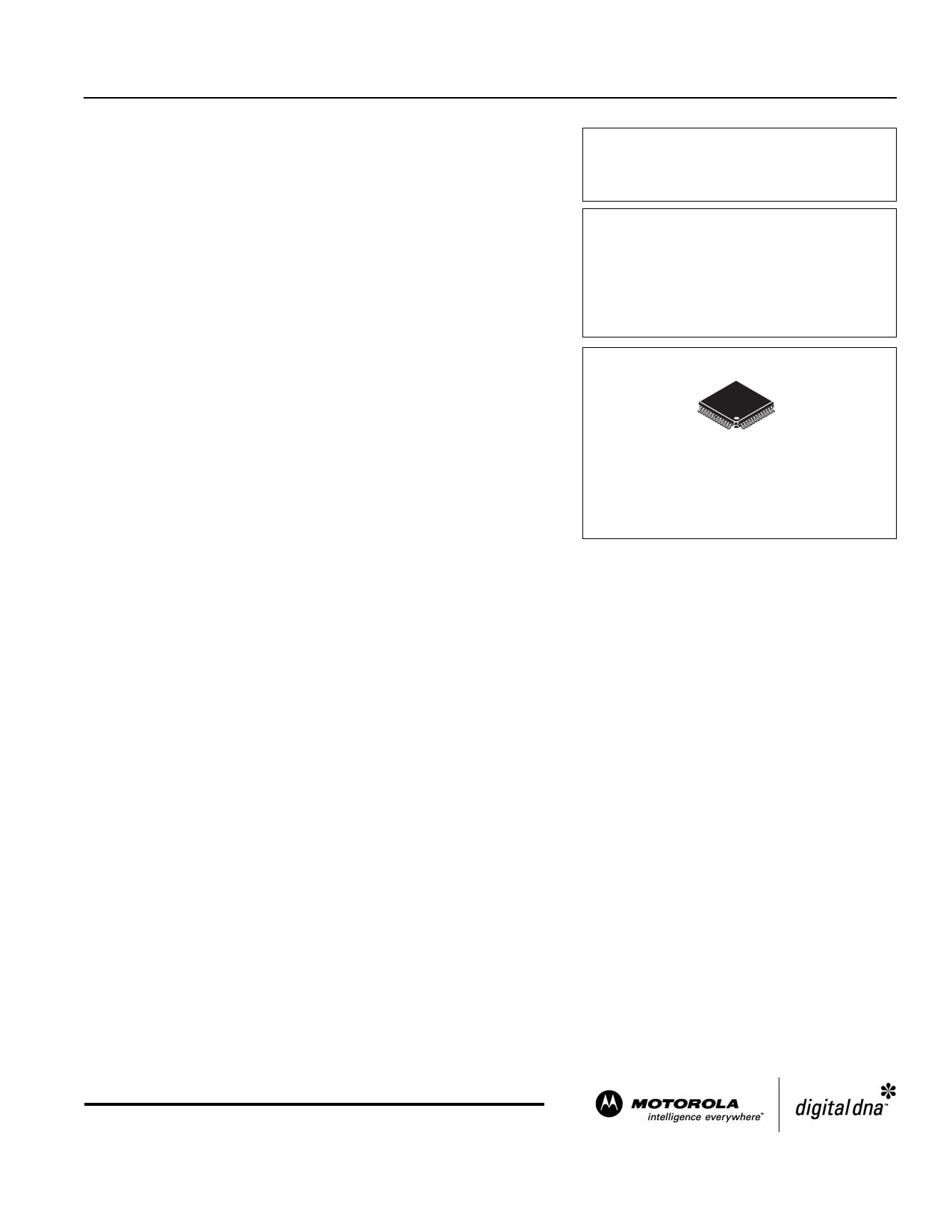
MPC9772
3.3V 1:12 LVCMOS
PLL CLOCK GENERATOR
FA SUFFIX
52 LEAD LQFP PACKAGE
CASE 848D
Functional Description
The MPC9772 utilizes PLL technology to frequency lock its outputs onto an input reference clock. Normal operation of the
MPC9772 requires the connection of the PLL feedback output QFB to feedback input FB_IN to close the PLL feedback path. The
reference clock frequency and the divider for the feedback path determine the VCO frequency. Both must be selected to match the
VCO frequency range. The MPC9772 features an extensive level of frequency programmability between the 12 outputs as well as
the output to input relationships, for instance 1:1, 2:1, 3:1, 3:2, 4:1, 4:3, 5:1, 5:2, 5:3, 5:4, 5:6, 6:1, 8:1 and 8:3.
The QSYNC output will indicate when the coincident rising edges of the above relationships will occur. The selectability of the feed-
back frequency is independent of the output frequencies. This allows for very flexible programming of the input reference versus out-
put frequency relationship. The output frequencies can be either odd or even multiples of the input reference. In addition the output
frequency can be less than the input frequency for applications where a frequency needs to be reduced by a non-binary factor. The
MPC9772 also supports the 180° phase shift of one of its output banks with respect to the other output banks. The QSYNC outputs
reflects the phase relationship between the QA and QC outputs and can be used for the generation of system baseline timing signals.
The REF_SEL pin selects the internal crystal oscillator or the LVCMOS compatible inputs as the reference clock signal. Two alter-
native LVCMOS compatible clock inputs are provided for clock redundancy support. The PLL_EN control selects the PLL bypass con-
figuration for test and diagnosis. In this configuration, the selected input reference clock is routed directly to the output dividers
bypassing the PLL. The PLL bypass is fully static and the minimum clock frequency specification and all other PLL characteristics do
not apply.
The outputs can be individually disabled (stopped in logic low state) by programming the serial CLOCK_STOP interface of the
MPC9772. The MPC9772 has an internal power-on reset.
The MPC9772 is fully 3.3V compatible and requires no external loop filter components. All inputs (except XTAL) accept LVCMOS
signals while the outputs provide LVCMOS compatible levels with the capability to drive terminated 50 Ω transmission lines. For series
terminated transmission lines, each of the MPC9772 outputs can drive one or two traces giving the devices an effective fanout of 1:24.
The device is pin and function compatible to the MPC972 and is packaged in a 52-lead LQFP package.
© Motorola, Inc. 2004
1 page 
MPC9772
Table 7. General Specifications
Symbol
Characteristics
VTT Output Termination Voltage
MM ESD Protection (Machine Model)
HBM ESD Protection (Human Body Model)
LU Latch-Up Immunity
CPD Power Dissipation Capacitance
CIN Input Capacitance
Min
200
2000
200
Typ
VCC ÷ 2
12
4.0
Max Unit Condition
V
V
V
mA
pF Per output
pF Inputs
Table 8. Absolute Maximum Ratings1
Symbol
Characteristics
Min Max Unit Condition
VCC Supply Voltage
–0.3 3.9 V
VIN DC Input Voltage
–0.3
VCC+0.3
V
VOUT DC Output Voltage
–0.3
VCC+0.3
V
IIN
IOUT
DC Input Current
DC Output Current
±20 mA
±50 mA
TS Storage Temperature
–65 125 °C
1. Absolute maximum continuous ratings are those maximum values beyond which damage to the device may occur. Exposure to these conditions
or conditions beyond those indicated may adversely affect device reliability. Functional operation at absolute-maximum-rated conditions is not
implied.
Table 9. DC Characteristics (VCC = 3.3V ± 5%, TA = –40° to 85°C)
Symbol
Characteristics
Min Typ Max Unit Condition
VCC_PLL PLL Supply Voltage
3.0 VCC V LVCMOS
VIH Input High Voltage
2.0
VCC + 0.3
V LVCMOS
VIL Input Low Voltage
0.8 V LVCMOS
VOH Output High Voltage
2.4
V IOH=–24 mA1
VOL Output Low Voltage
0.55
0.30
V IOL= 24 mA
V IOL= 12 mA
ZOUT Output Impedance
14 – 17
W
IIN Input Current2
±200
µA VIN = VCC or GND
ICC_PLL Maximum PLL Supply Current
3.0 5.0 mA VCC_PLL Pin
ICCQ Maximum Quiescent Supply Current
15 mA All VCC Pins
1. The MPC9772 is capable of driving 50Ω transmission lines on the incident edge. Each output drives one 50Ω parallel terminated transmission
line to a termination voltage of VTT. Alternatively, the device drives up to two 50Ω series terminated transmission lines.
2. Inputs have pull-down resistors affecting the input current.
TIMING SOLUTIONS
5
MOTOROLA
5 Page 
Power Supply Filtering
The MPC9772 is a mixed analog/digital product. Its analog
circuitry is naturally susceptible to random noise, especially if
this noise is seen on the power supply pins. Random noise on
the VCC_PLL power supply impacts the device characteristics,
for instance I/O jitter. The MPC9772 provides separate power
supplies for the output buffers (VCC) and the phase-locked loop
(VCC_PLL) of the device. The purpose of this design technique
is to isolate the high switching noise digital outputs from the
relatively sensitive internal analog phase-locked loop. In a
digital system environment where it is more difficult to minimize
noise on the power supplies a second level of isolation may be
required. The simple but effective form of isolation is a power
supply filter on the VCCA_PLL pin for the MPC9772. Figure 7
illustrates a typical power supply filter scheme. The MPC9772
frequency and phase stability is most susceptible to noise with
spectral content in the 100kHz to 20MHz range. Therefore the
filter should be designed to target this range. The key
parameter that needs to be met in the final filter design is the DC
voltage drop across the series filter resistor RF. From the data
sheet the ICC_PLL current (the current sourced through
the VCC_PLL pin) is typically 3 mA (5 mA maximum), assuming
that a minimum of 3.0V must be maintained on the VCC_PLL pin.
The resistor RF shown in Figure 7 must have a resistance of
5-10Ω to meet the voltage drop criteria.
RF = 5–10Ω
CF = 22 µF
RF
VCC
VCC_PLL
CF 10 nF
MPC9772
33...100 nF
VCC
Figure 7. VCC_PLL Power Supply Filter
The minimum values for RF and the filter capacitor CF are
defined by the required filter characteristics: the RC filter should
provide an attenuation greater than 40 dB for noise whose
spectral content is above 100 kHz. In the example RC filter
shown in Figure 7. “VCC_PLL Power Supply Filter”, the filter
cut-off frequency is around 4.5 kHz and the noise attenuation at
100 kHz is better than 42 dB.
As the noise frequency crosses the series resonant point of
an individual capacitor its overall impedance begins to look
inductive and thus increases with increasing frequency. The
parallel capacitor combination shown ensures that a low
impedance path to ground exists for frequencies well above the
bandwidth of the PLL. Although the MPC9772 has several
design features to minimize the susceptibility to power supply
noise (isolated power and grounds and fully differential PLL)
there still may be applications in which overall performance is
being degraded due to system power supply noise. The power
MPC9772
supply filter schemes discussed in this section should be
adequate to eliminate power supply noise related problems in
most designs.
Using the MPC9772 in Zero-Delay Applications
Nested clock trees are typical applications for the MPC9772.
Designs using the MPC9772 as LVCMOS PLL fanout buffer
with zero insertion delay will show significantly lower clock skew
than clock distributions developed from CMOS fanout buffers.
The external feedback option of the MPC9772 clock driver
allows for its use as a zero delay buffer. The PLL aligns the
feedback clock output edge with the clock input reference edge
resulting a near zero delay through the device (the propagation
delay through the device is virtually eliminated). The maximum
insertion delay of the device in zero-delay applications is
measured between the reference clock input and any output.
This effective delay consists of the static phase offset, I/O jitter
(phase or long-term jitter), feedback path delay and the
output-to-output skew error relative to the feedback output.
Calculation of Part-to-Part Skew
The MPC9772 zero delay buffer supports applications where
critical clock signal timing can be maintained across several
devices. If the reference clock inputs of two or more MPC9772
are connected together, the maximum overall timing uncertainty
from the common CCLKx input to any output is:
tSK(PP) = t(∅) + tSK(O) + tPD, LINE(FB) + tJIT(∅) ⋅ CF
This maximum timing uncertainty consist of 4 components:
static phase offset, output skew, feedback board trace delay
and I/O (phase) jitter:
CCLKCommon
–t(∅)
tPD,LINE(FB)
QFBDevice 1
Any QDevice 1
tJIT(∅)
+tSK(O)
QFBDevice2
+t(∅)
tJIT(∅)
Any QDevice 2
Max. skew
+tSK(O)
tSK(PP)
Figure 8. MPC9772 Maximum
Device-to-Device Skew
Due to the statistical nature of I/O jitter a RMS value (1 σ) is
specified. I/O jitter numbers for other confidence factors (CF)
can be derived from Table 12.
TIMING SOLUTIONS
11
MOTOROLA
11 Page | ||
| Páginas | Total 16 Páginas | |
| PDF Descargar | [ Datasheet MPC9772.PDF ] | |
Hoja de datos destacado
| Número de pieza | Descripción | Fabricantes |
| MPC9772 | 3.3V 1:12 LVCMOS PLL Clock Generator | IDT |
| MPC9772 | 3.3V 1:12 LVCMOS PLL Clock Generator | Motorola Semiconductors |
| MPC9773 | 3.3 V 1:12 LVCMOS PLL Clock Generator | Freescale Semiconductor |
| MPC9774 | LVCMOS PLL CLOCK GENERATOR | Motorola Semiconductors |
| Número de pieza | Descripción | Fabricantes |
| SLA6805M | High Voltage 3 phase Motor Driver IC. |
Sanken |
| SDC1742 | 12- and 14-Bit Hybrid Synchro / Resolver-to-Digital Converters. |
Analog Devices |
|
DataSheet.es es una pagina web que funciona como un repositorio de manuales o hoja de datos de muchos de los productos más populares, |
| DataSheet.es | 2020 | Privacy Policy | Contacto | Buscar |