|
|
|
PDF FOD2711 Data sheet ( Hoja de datos )
| Número de pieza | FOD2711 | |
| Descripción | optically isolated error amplifier | |
| Fabricantes | Fairchild Semiconductor | |
| Logotipo | ||
Hay una vista previa y un enlace de descarga de FOD2711 (archivo pdf) en la parte inferior de esta página. Total 15 Páginas | ||
|
No Preview Available !
OPTICALLY ISOLATED
ERROR AMPLIFIER
FOD2711
DESCRIPTION
The FOD2711 Optically Isolated Amplifier consists of the popular RC431A precision
programmable shunt reference and an optocoupler. The optocoupler is a gallium arsenide
(GaAs) light emitting diode optically coupled to a silicon phototransistor. The reference
voltage tolerance is 1%. The current transfer ratio (CTR) ranges from 100% to 200%.
It is primarily intended for use as the error amplifier/reference voltage/optocoupler
function in isolated ac to dc power supplies and dc/dc converters.
8
1
When using the FOD2711, power supply designers can reduce the component count and
save space in tightly packaged designs. The tight tolerance reference eliminates the need
for adjustments in many applications.
The device comes in a 8-pin dip white package.
8
1
8
1
FEATURES
• Optocoupler, precision reference and error amplifier in single package
• 1.240V ± 1% reference
• CTR 100% to 200%
• 5,000V RMS isolation
• UL approval E90700, Volume 2
CSA approval 1296837
VDE approval 40002463
BSI approval 8702, 8703
APPLICATIONS
• Power supplies regulation
• DC to DC converters
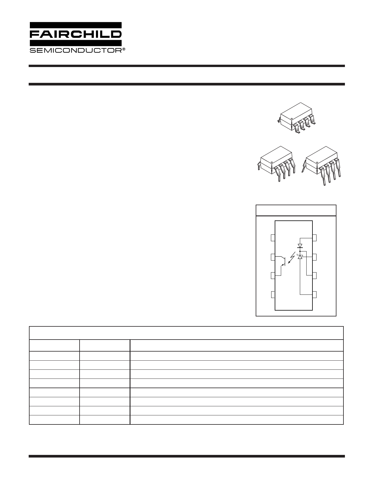
FUNCTIONAL BLOCK DIAGRAM
NC 1
C2
E3
NC 4
8 LED
7 FB
6 COMP
5 GND
PIN DEFINITIONS
Pin Number
1
2
3
4
5
6
7
8
Pin Name
NC
C
E
NC
GND
COMP
FB
LED
Pin function description
Not connected
Phototransistor Collector
Phototransistor Emitter
Not connected
Ground
Error Amplifier Compensation. This pin is the output of the error amplifier. *
Voltage Feedback. This pin is the inverting input to the error amplifier
Anode LED. This pin is the input to the light emitting diode.
* The compensation network must be attached between pins 6 and 7.
© 2003 Fairchild Semiconductor Corporation
Page 1 of 15
4/14/03
1 page 
OPTICALLY ISOLATED
ERROR AMPLIFIER
FOD2711
I(LED)
8
VF
6
V7
VREF
5
2
3
V
I(LED)
8
2
R1 6
7
R2 VREF
5
VCOMP
3
FIG. 1. VREF, VF, ILED (min) TEST CIRCUIT
FIG. 2. ∆VREF/∆VCOMP TEST CIRCUIT
I(LED)
8
IREF
6
V7
R1
5
2
3
FIG. 3. IREF TEST CIRCUIT
ICEO
82
VCE
6
3
7
5
I(OFF)
V(LED)
V
8
6
7
5
2
3
FIG. 4. I(OFF) TEST CIRCUIT
I(LED)
V
8
6
7
VREF
5
IC
2
VCE
3
VCOMP
FIG. 5. ICEO TEST CIRCUIT
© 2003 Fairchild Semiconductor Corporation
Page 5 of 15
FIG. 6. CTR, VCE(sat) TEST CIRCUIT
4/14/03
5 Page 
OPTICALLY ISOLATED
ERROR AMPLIFIER
Package Dimensions (Through Hole)
FOD2711
Package Dimensions (0.4"Lead Spacing)
43
56
21
78
PIN 1
ID.
0.270 (6.86)
0.250 (6.35)
0.200 (5.08)
0.140 (3.55)
0.022 (0.56)
0.016 (0.41)
0.390 (9.91)
0.370 (9.40)
0.070 (1.78)
0.045 (1.14)
0.020 (0.51) MIN
0.154 (3.90)
0.120 (3.05)
0.100 (2.54) TYP
0.016 (0.40)
0.008 (0.20)
15° MAX
0.300 (7.62)
TYP
Package Dimensions (Surface Mount)
0.390 (9.91)
0.370 (9.40)
4 32 1
PIN 1
ID.
0.270 (6.86)
0.250 (6.35)
5 67 8
0.070 (1.78)
0.045 (1.14)
0.300 (7.62)
TYP
0.020 (0.51)
MIN
0.016 (0.41)
0.008 (0.20)
0.022 (0.56)
0.016 (0.41)
0.100 (2.54)
TYP
Lead Coplanarity : 0.004 (0.10) MAX
0.045 [1.14]
0.315 (8.00)
MIN
0.405 (10.30)
MIN
43
21
PIN 1
ID.
0.270 (6.86)
0.250 (6.35)
56
78
0.200 (5.08)
0.140 (3.55)
0.022 (0.56)
0.016 (0.41)
0.390 (9.91)
0.370 (9.40)
0.070 (1.78)
0.045 (1.14)
0.004 (0.10) MIN
0.154 (3.90)
0.120 (3.05)
0.100 (2.54) TYP
0.016 (0.40)
0.008 (0.20)
8 - Pin Dip
0° to 15°
0.400 (10.16)
TYP
0.070 (1.78)
0.060 (1.52)
0.295 (7.49)
0.415 (10.54)
0.100 (2.54)
0.030 (0.76)
NOTE
All dimensions are in inches (millimeters)
© 2003 Fairchild Semiconductor Corporation
Page 11 of 15
4/14/03
11 Page | ||
| Páginas | Total 15 Páginas | |
| PDF Descargar | [ Datasheet FOD2711.PDF ] | |
Hoja de datos destacado
| Número de pieza | Descripción | Fabricantes |
| FOD2711 | optically isolated error amplifier | Fairchild Semiconductor |
| FOD2712 | OPTICALLY ISOLATED ERROR AMPLIFIER | Fairchild Semiconductor |
| FOD2712 | Power Conversion for the Data Communications Market | Fairchild Semiconductor |
| Número de pieza | Descripción | Fabricantes |
| SLA6805M | High Voltage 3 phase Motor Driver IC. |
Sanken |
| SDC1742 | 12- and 14-Bit Hybrid Synchro / Resolver-to-Digital Converters. |
Analog Devices |
|
DataSheet.es es una pagina web que funciona como un repositorio de manuales o hoja de datos de muchos de los productos más populares, |
| DataSheet.es | 2020 | Privacy Policy | Contacto | Buscar |