|
|
|
PDF NJG1148MD7 Data sheet ( Hoja de datos )
| Número de pieza | NJG1148MD7 | |
| Descripción | 5GHz BAND LOW NOISE AMPLIFIER GaAs MMIC | |
| Fabricantes | New Japan Radio | |
| Logotipo | ||
Hay una vista previa y un enlace de descarga de NJG1148MD7 (archivo pdf) en la parte inferior de esta página. Total 17 Páginas | ||
|
No Preview Available !
NJG1148MD7
5GHz BAND LOW NOISE AMPLIFIER GaAs MMIC
I GENERAL DESCRIPTION
NJG1148MD7 is a 5GHz band low noise amplifier GaAs MMIC
designed for wireless LAN, wireless image transmission and
Intelligent Transport System.
The NJG1148MD7 has a LNA pass-through function to select
high gain mode or low gain mode by low control voltage operation.
Within the wide dynamic range from 4.9~5.95GHz, the
NJG1148MD7 achieves low noise figure and high linearity with
fewer external components. The ESD protection circuits are
integrated into the MMIC. They achieve high ESD protection
voltage.
A small and ultra-thin package of EQFN14-D7 is adopted.
I PACKAGE OUTLINE
NJG1148MD7
I APPLICATIONS
5GHz Band application from 4.9GHz to 5.95GHz
Wireless LAN, wireless image transmission and Intelligent transport System applications
I FEATURES
G Operating voltage
G Low current consumption
G High Gain
G Low Noise figure
G High IIP3
G Low Insertion Loss
G Few external components
G Small package size
G Pb free, Halogen free
3.3V
7.0mA typ. @VDD=3.3V, VCTL=1.8V (LNA mode)
5µA typ. @VDD=3.3V, VCTL=0V (Bypass mode)
12.5dB typ. @VDD=3.3V, VCTL=1.8V (LNA mode)
1.5dB typ. @VDD=3.3V, VCTL=1.8V (LNA mode)
+5.0dBm typ. @VDD=3.3V, VCTL=1.8V (LNA mode)
5.0dB typ. @VDD=3.3V, VCTL=0V (Bypass mode)
1pc (Bypass Capacitor)
EQFN14-D7 (Package size: 1.6mm x 1.6mm x 0.397mm typ.)
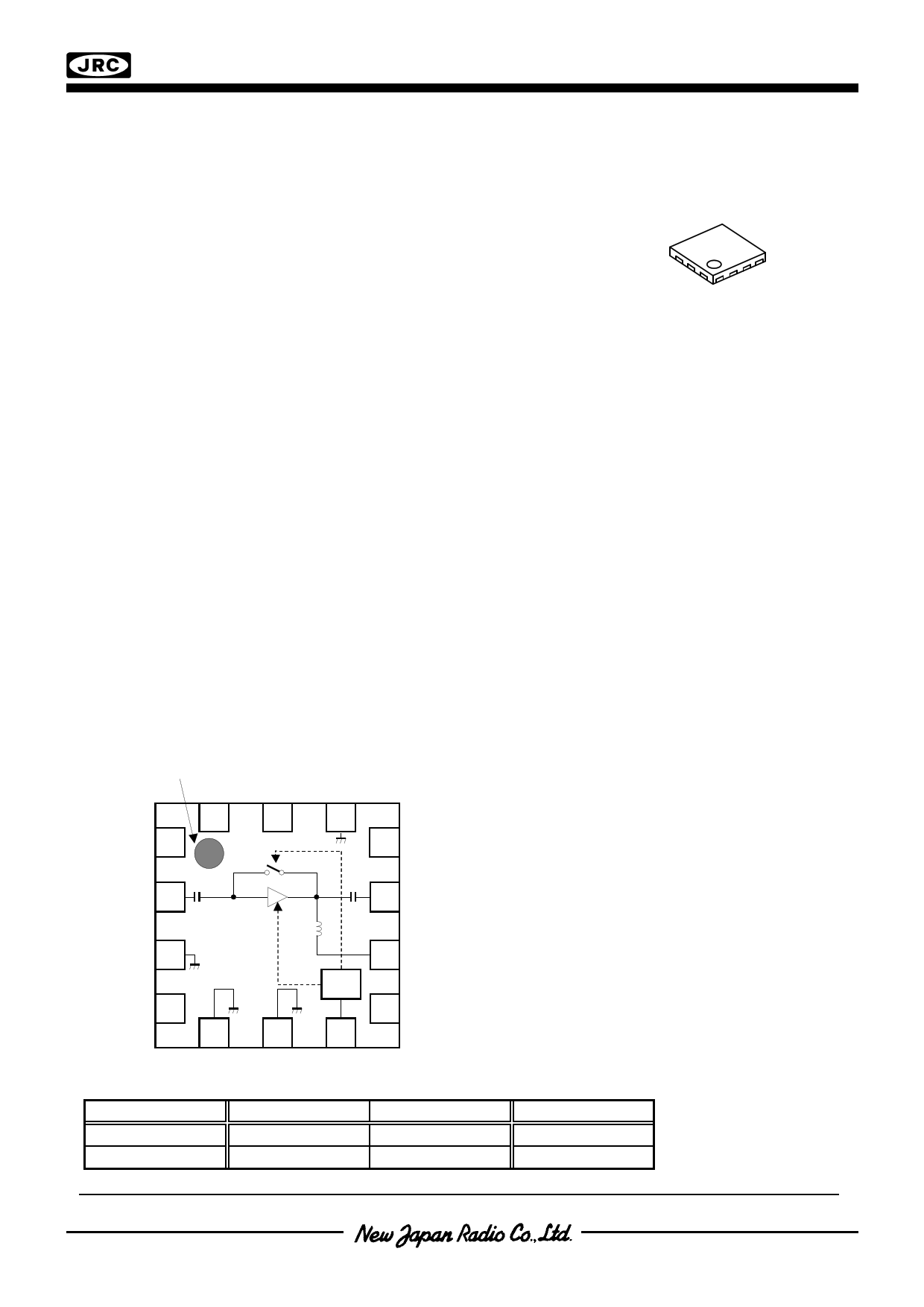
I PIN CONFIGURATION
1PIN INDEX
(Top view)
NC(GND)
NC(GND)
GND
14 13 12
1
NC(GND)
Bypass
circuit
11
NC(GND)
2
RFIN
LNA circuit
10
RFOUT
39
GND
Logic
circuit
VDD
48
NC(GND) 5 6 7 NC(GND)
GND
GND
VCTL
Pin Connection
1. NC (GND)
2. RFIN
3. GND
4. NC (GND)
5. GND
6. GND
7. VCTL
8. NC (GND)
9. VDD
10. RFOUT
11. NC (GND)
12. GND
13. NC (GND)
14. NC (GND)
I TRUTH TABLE
VCTL
H
L
“H”=VCTL(H)“L”=VCTL(L)
LNA Circuit
Bypass Circuit
ON OFF
OFF
ON
Operating mode
LNA mode
Bypass mode
Note: Specifications and description listed in this datasheet are subject to change without notice
Ver.2014-05-22
-1-
1 page 
NJG1148MD7
I ELECTRICAL CHARACTERISTICS (LNA mode)
Conditions: VDD=3.3V, VCTL=1.8V, Ta=25oC, Zs=Zl=50Ω, with application circuit
Pout vs. Pin
(f=5500MHz)
15
10
5 P-1dB(OUT)=8.6dBm
0
-5
Pout
-10
-15
-20
-25
P-1dB(IN)=-2.5dBm
-30
-40 -35 -30 -25 -20 -15 -10 -5
Pin (dBm)
0
Gain, IDD vs. Pin
(f=5500MHz)
15
Gain
10
20
15
5 10
IDD
0
5
P-1dB(IN)=-2.5dBm
-5
-40 -35 -30 -25 -20 -15 -10 -5
Pin (dBm)
0
0
Pout, IM3 vs. Pin
(f1=5500MHz, f2=f1+100kHz)
40
OIP3=+18.7dBm
20
0 Pout
-20
-40
-60 IM3
-80
-100
-30 -25 -20 -15 -10
IIP3=+6.9dBm
-5 0
5
Pin (dBm)
10
Gain, NF vs. frequency
15 4
Gain
14
3.5
13 3
12 2.5
11 2
10 1.5
9 NF
1
8
(Exclude PCB, connector losses)
7
4000
4500
5000
5500
6000
freqency (MHz)
6500
0.5
0
7000
-5-
5 Page 
NJG1148MD7
I ELECTRICAL CHARACTERISTICS (Bypass mode)
Conditions: VDD=3.3V, VCTL=0V, Ta=25oC, Zs=Zl=50Ω, with application circuit
Pout vs. Pin
(f=5500MHz)
20
P-1dB(OUT)=8.1dBm
10
0
Pout
-10
-20
P-1dB(IN)=+13.0dBm
-30
-20 -15 -10 -5 0 5 10
Pin (dBm)
15
Loss, IDD vs. Pin
(f=5500MHz)
3
Loss
4
20.0
16.0
5 12.0
6
IDD
8.0
7 4.0
8
-20 -15 -10
P-1dB(IN)=+13.0dBm
-5 0
5
Pin (dBm)
10
0.0
15
Pout, IM3 vs. Pin
(f1=5500MHz, f2=f1+100kHz)
20
OIP3=+6.9dBm
0
Pout
-20
-40
IM3
-60
-80
IIP3=+10.8dBm
-100
-20 -15 -10
-5
0
5 10 15
Pin (dBm)
P-1dB(IN) vs. frequency
(f=4900~5950MHz)
25
20
15
P-1dB(IN)
10
5
4500
5000
5500
frequency (MHz)
6000
Loss vs. frequency
0
2
4
Loss
6
8
(Exclude PCB, connector losses)
10
4000
4500
5000
5500
6000
frequency(MHz)
6500
7000
OIP3, IIP3 vs. frequency
(f1=4900~5950MHz, f2=f1+100kHz, Pin=-10dBm)
16
14
12 IIP3
10
8
6
4
4500
OIP3
5000
5500
frequency (MHz)
6000
- 11 -
11 Page | ||
| Páginas | Total 17 Páginas | |
| PDF Descargar | [ Datasheet NJG1148MD7.PDF ] | |
Hoja de datos destacado
| Número de pieza | Descripción | Fabricantes |
| NJG1148MD7 | 5GHz BAND LOW NOISE AMPLIFIER GaAs MMIC | New Japan Radio |
| Número de pieza | Descripción | Fabricantes |
| SLA6805M | High Voltage 3 phase Motor Driver IC. |
Sanken |
| SDC1742 | 12- and 14-Bit Hybrid Synchro / Resolver-to-Digital Converters. |
Analog Devices |
|
DataSheet.es es una pagina web que funciona como un repositorio de manuales o hoja de datos de muchos de los productos más populares, |
| DataSheet.es | 2020 | Privacy Policy | Contacto | Buscar |